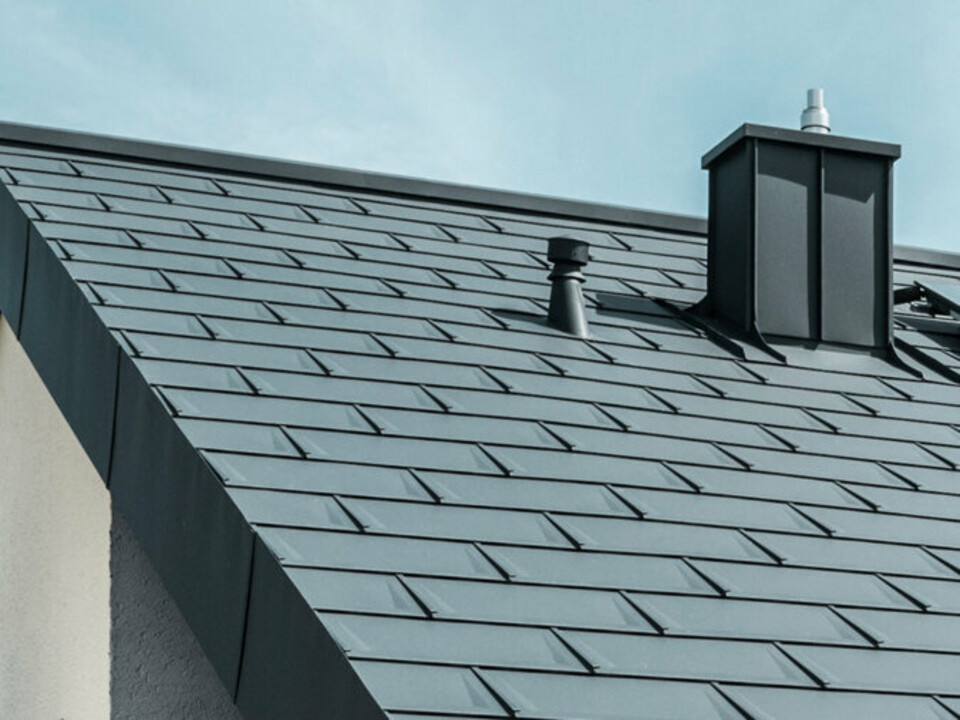
with PREFALZ in P.10 dark grey")


colour |
uncoated |
|---|---|
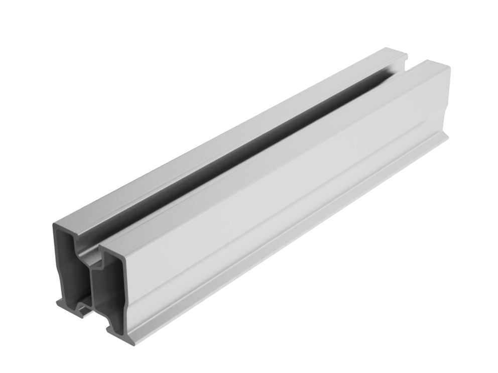
Material |
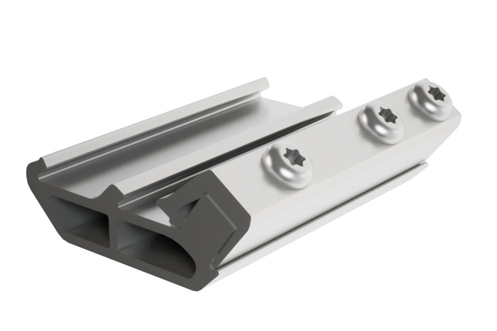
aluminium (EN AW 6005A) |
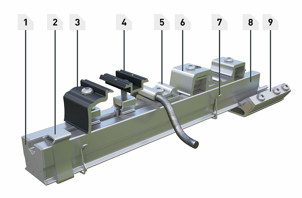
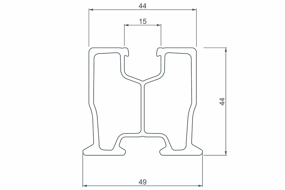
Length |
3,600 mm |
Dimension (width/height) |
49 mm / 44 mm |
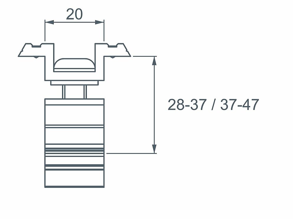
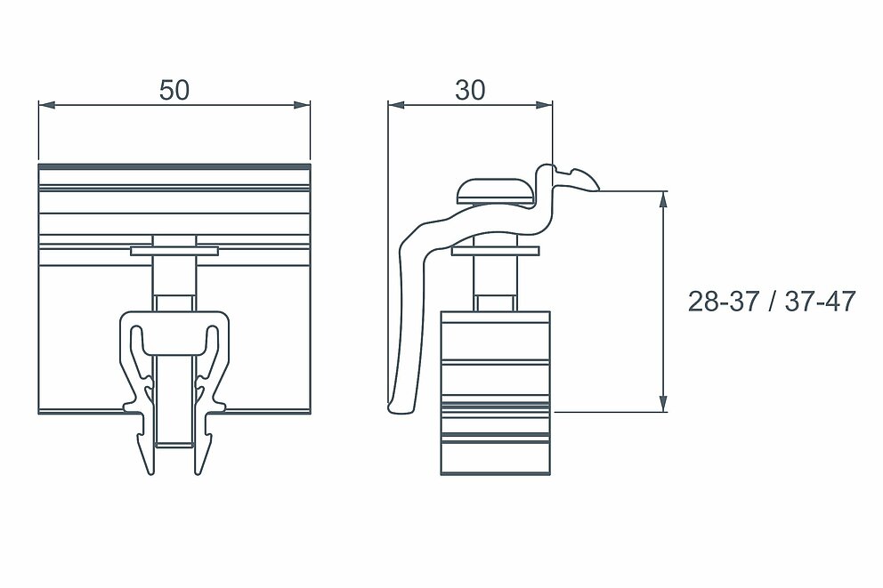
solar panels |
for framed photovoltaic modules (frame height: 28 - 47 mm) |
panel orientation |
according to the manufacturer’s guidelines |
colour |
uncoated or black anodised |
|---|---|
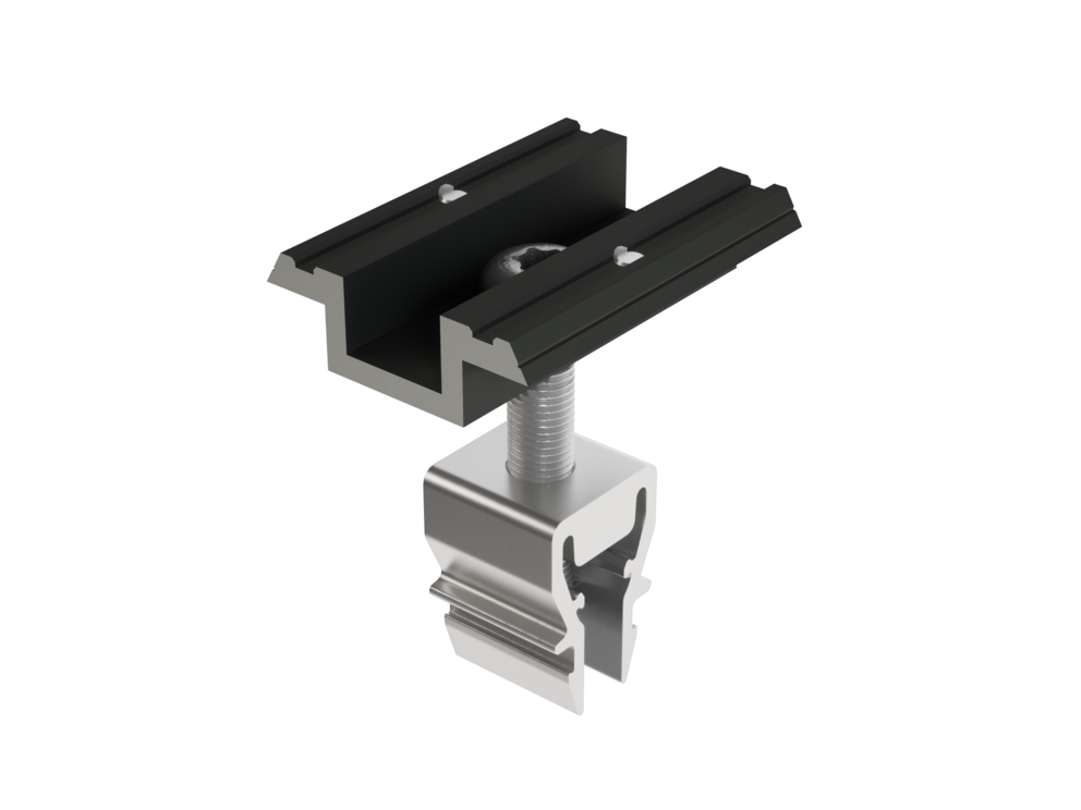
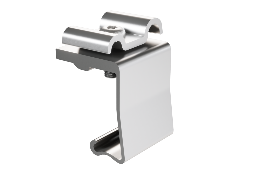
components |
Middle clamp with pin 28 - 37 mm, aluminium Middle clamp with pin 37 - 47 mm, aluminium |
Torque |
15 Nm |


colour |
uncoated or black anodised |
|---|---|
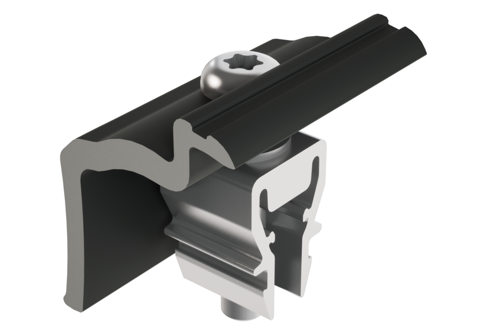
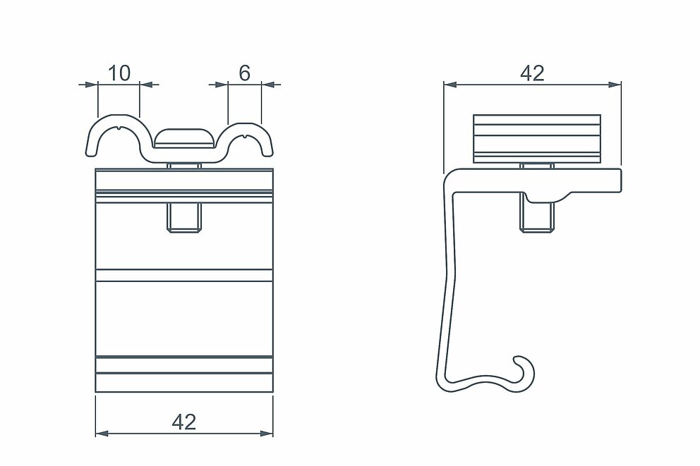
components |
End clamp 28 - 37 mm, aluminium End clamp 37 - 47 mm, aluminium |
Torque |
15 Nm |
components |
Earth connector Ø 8 and Ø 10 mm |
|---|---|
Torque |
15 Nm |
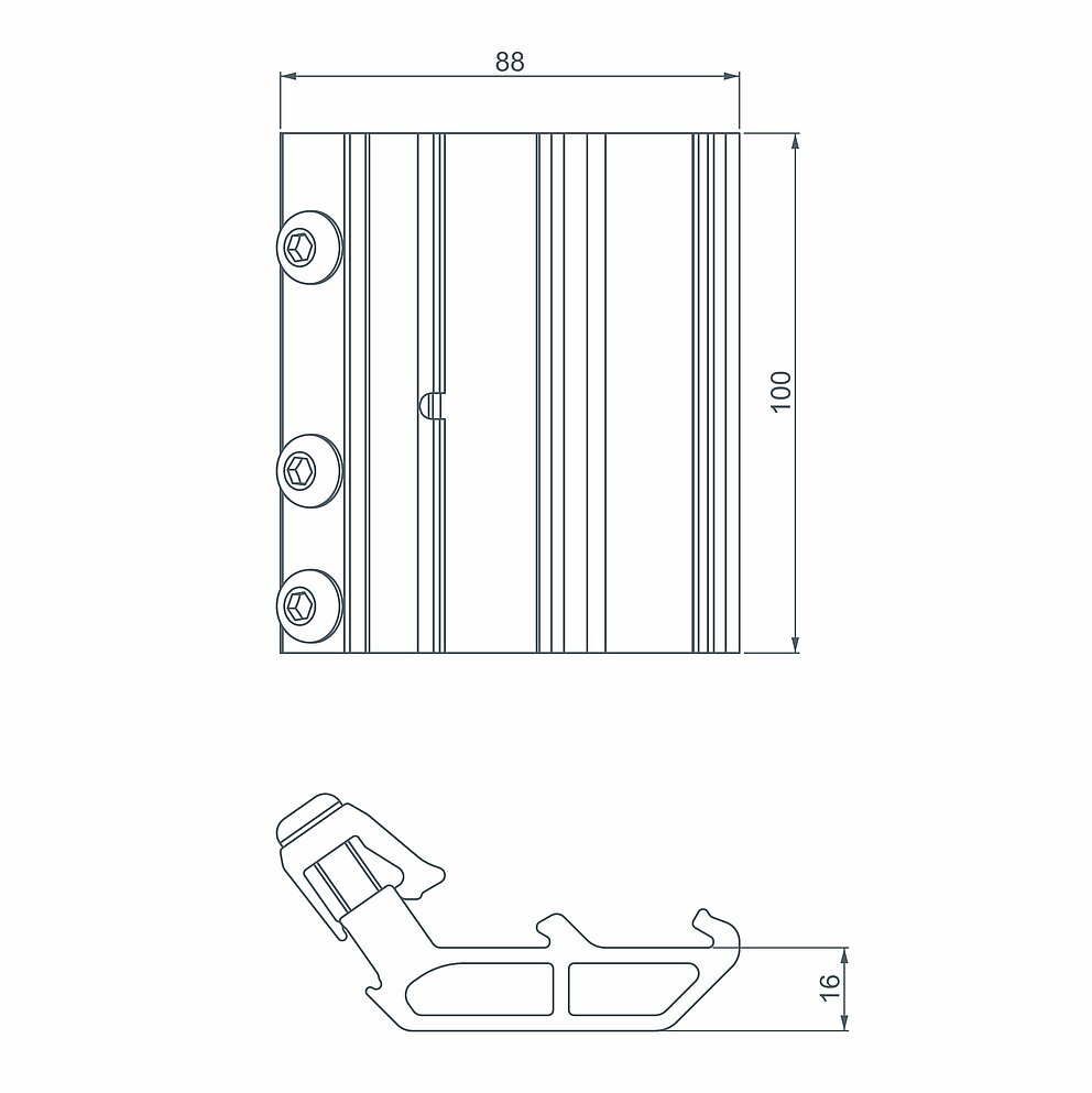
Material |
Aluminium (EN AW 6060T66) |
|---|---|
Length |
100 mm |
components |
Base body (EN AW 6060T66) |
Torque |
20 Nm |
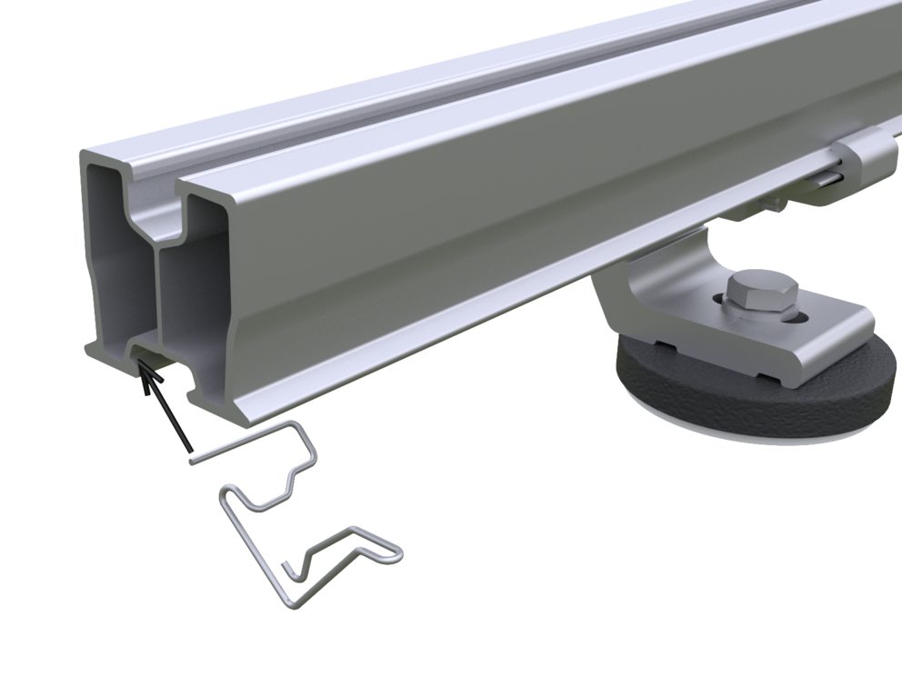
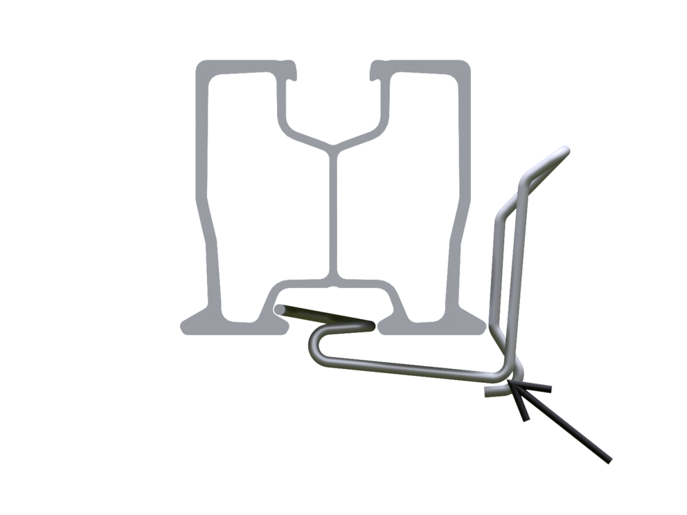
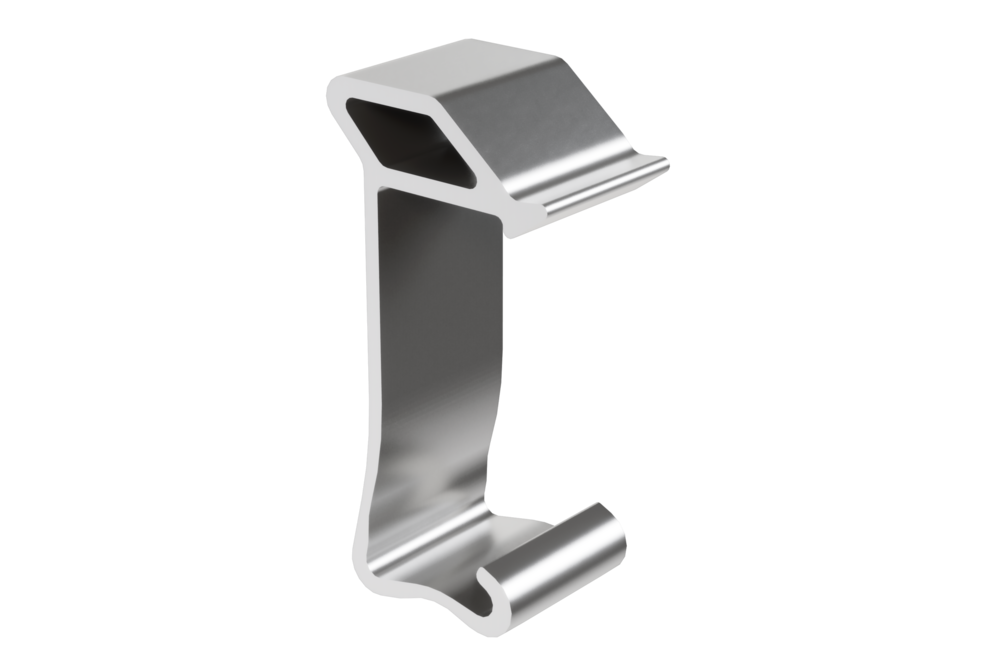
Material |
Stainless spring steel wire Ø 1.8 mm |
|---|
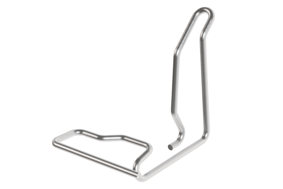
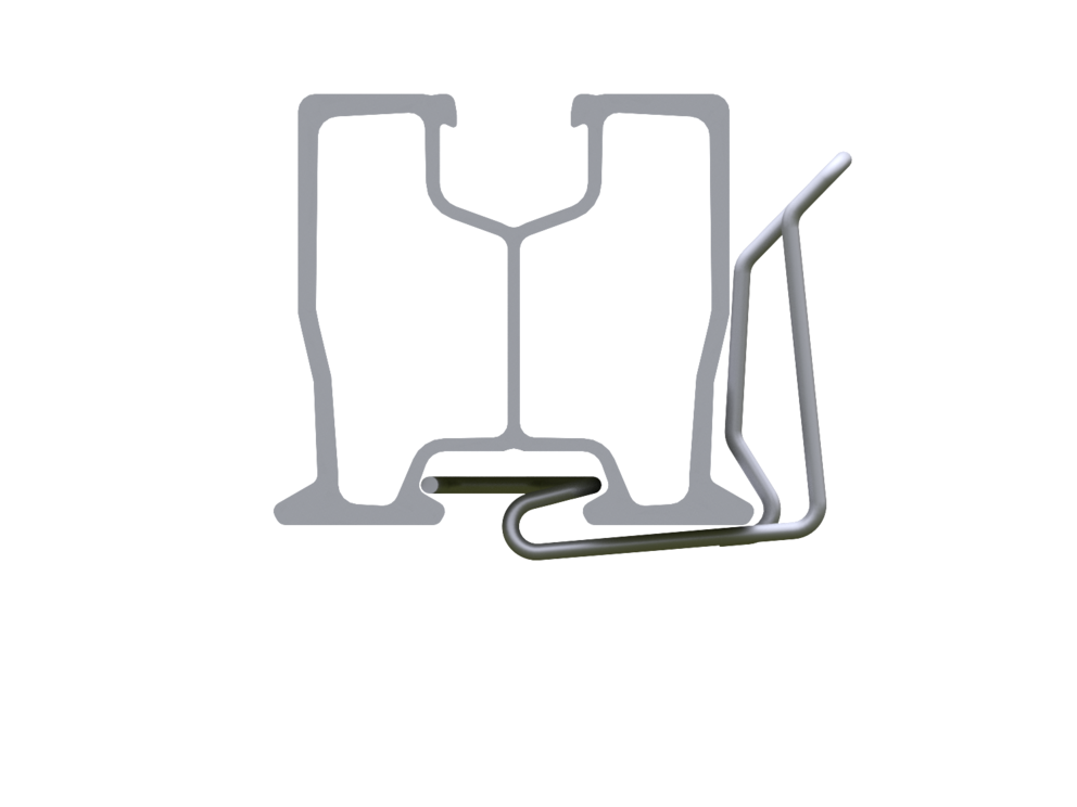
The cable clip is inserted diagonally from below into the groove of the rail and clipped into the rail by applying pressure diagonally upwards.
Material |
Aluminium (EN AW 6060T66) |
|---|
To prevent photovoltaic modules from falling, solar panel fall protection devices are installed in the PREVARIO solar mounting system. Two solar panel fall protection devices per module are clamped onto the upper module rail in the lowest module row of a generator area. This ensures that if a panel falls, the upper edge of its frame remains attached to the protection device. A protection device which has been activated is only a short-term safety solution Affected modules should be reinstalled immediately.
You can only download content from one product category. If you require content from multiple categories, please create a separate download for each product area.