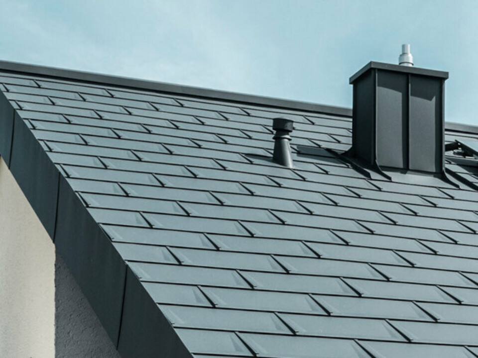
with PREFALZ in P.10 dark grey")


Click on the topic you want to go directly to the appropriate guide:

The eaves overhang of the starter strip should be in the rear third of the gutter width and may not exceed 80 mm.
Measure from the planned top of the first roof tile 450 mm towards the eaves (ensure that the eaves overhang is between 30 and 80 mm). Make 150 mm (starter strip width) from below a mark (= starter strip width upper edge).
Repeat the respective process on the second side of the eaves and connect these marks with a horizontal chalk line.
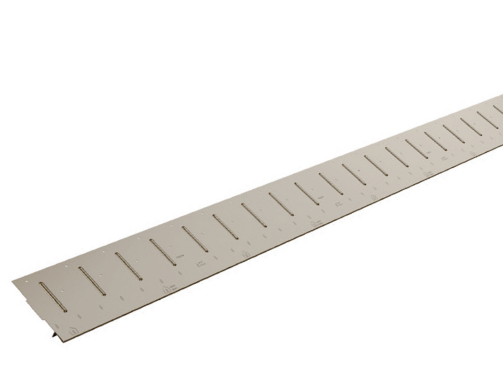
The starter strip is to be nailed storm-proof (nail out all pre-punched holes). Pin the starter strip through before nailing out any pre-punched holes with the supplied PREFA nails.
Note
The more precisely you install the starter strip, the easier it will be for you to professionally lay the PREFA roof system.
Make sure that the starter strip is installed under the separation layer.

The eaves overhang of the starter strip should be in the rear third of the gutter width and may not exceed 80 mm.
The starter strip is attached in a straight line over the entire length of the eaves with the help of a cord cut off beforehand.
The starter strip is to be nailed storm-proof (nail out all pre-punched holes).
This is followed by the vertical angular impact.
Pin the starter strip through before nailing out any pre-punched holes with the supplied PREFA nails.

Note
The more precisely you install the starter strip, the easier it will be for you to professionally lay the PREFA roof system. Markings (lacing dimensions) are provided as an aid for the respective PREFA roof coverings.
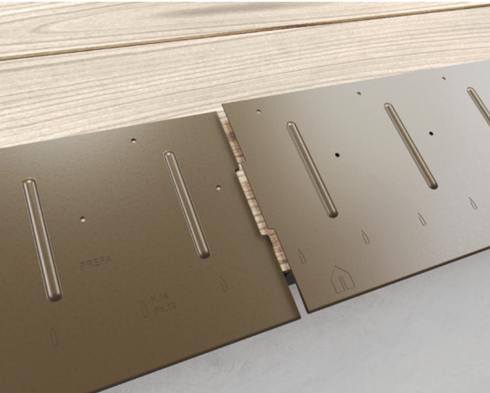
Make sure that the starter strip is installed under the separation layer (see figure above).
Align the starter strip with the embossed markings for R.16 roof tile or FX.12 roof panel to the middle of the roof.
It should be noted that the area for the lateral upstand (e.g. verge formation) is not in the rebate area of the R.16 roof tile or FX.12 roof panel. If necessary, move the starter strip by a quarter of the dimension of an R.16 roof tile or an FX.12 roof panel.

Align the starter strip with the embossed markings to the middle of the roof.
It should be noted that the area for the lateral upstand (e.g. verge formation) is not in the centre of the rhomboid roof tiles 29 × 29 or
44 × 44. If necessary, move the starter strip by a quarter of the dimension (1/4 of the vertical lacing dimension) of a rhomboid roof tile 29 × 29 or 44 × 44.


Notch the upper patent fold in the area of the raised edge so that a hook fold remains (Fig. 1 and 2), and bend the R.16 roof tile or the FX.12 roof panel upwards 30 mm at a right angle to the roof surface.
With each left-hand upstand of the shingle (verge flashing and edging), the folds running diagonally downwards are to be notched in order to avoid any capillary action.


Variantions with shortened shingles or fitted shingles.
Other variants are to place the sloping seams with a shortened roof shingle or with a fitting shingle outside of the upstand area.
Variant 1: Shortened shingle
Shorten and cover the last shingle before edging up (Fig. 7 and 8).


Variant 2: Fitting shingle
Attach fitting shingles, cut with a fold allowance of 30 mm and edge it up (Fig. 8 and 9).


Only a professional installation guarantees a rainproof roof.
After preparing the shingle, the connection flashing (e.g. gable cladding or wall connection cove) can be produced and worked into the covering.
With each left-hand upstand of the DS.19 shingle (verge flashing and edging), the folds running diagonally downwards are to be notched in order to avoid any capillary action.


Variant DS.19 fitting shingle
One variant is the sloping seams with a DS.19 fitting shingle outside of the upstand area.


Note
The DS.19 fitting shingle is not suitable to cover a entire roof.
CAUTION: Shortening of a DS.19 shingle is not possible due to the capillary beads.
Only a professional installation guarantees a rainproof roof.
After preparing the DS.19 shingle, the joint flashing (e.g. edge cladding or wall connection cove) can be executed and worked into the roof covering.
With each lateral upstand of the rhomboid roof tile 29 × 29 (verge flashing and edging), the folds running diagonally downwards are to be cut out and bent up on the underside.


Only a professional installation guarantees a rainproof roof.
After preparing the rhomboid roof tiles 29 × 29, the connection flashing (e.g. gable cladding or wall connection cove) can be executed and worked into the roof covering.
With each lateral upstand of the rhomboid roof tile 44 × 44 (verge flashing and edging), the folds running diagonally downwards are to be cut out and bent up on the underside.


Only a professional installation guarantees a rainproof roof.
After preparing the rhomboid roof tiles 44 × 44, the connection flashing (e.g. gable cladding or wall connection cove) can be executed and worked into the roof covering.


1 Roof tile |
4 Valley flashing |
The safety valley is a recommendation of the PREFA company.
In general the installer decides the use of a safety valley based upon his skills and experience. Compared to common valley flashings, the safetyvalley offers increased safety with regard to backwater in the sensitivevalley area.
Advantages of the safety valley:


1 Roof tile |
4 Valley flashing |


The covering direction should always be selected in the direction of thevalley. As a result, if snow and ice slides off in this area, the overlap groove is prevented from bending up.


Note
For shingles and DS.19 shingles, the intersection point on the left hand side of the valley must be avoided.
Roof shingle
If the intersection point coincides with the valley on the left-hand side, a shortened shingle (1) or fitting shingle (1) must be assembled and installed.

DS.19 shingle
In the case of DS.19 shingles, if the collar/shingle joint intersection coincides with the valley on the left-hand side, a DS.19 fitting shingle (1) must be laid beforehand.
Shortening of a DS.19 shingle is not possible due to the capillary beads.


Note
When using the safety valley, the valley joint can also be designed in such a way that the valley/panel joint intersection point coincides.
Depending on roof structure and functionally, there are various options.

The ridge ventcan be used for roof pitches of 12-55°.
The original PREFA ridge vent has an apron on both sides. Nevertheless, raise the roof covering 40 mm to achieve a rainproof connection.
Fasten the last (cut, if required) row of tiles with a return clip, by means of a direct fastening to the side of the bead of the underlying bead (with PREFA roof panels) or by means of a direct fastening above the foam wedge of the jet fan.
Installation


Note
Make sure that the foam wedge is attached to the entire length of the roof covering.
Note
When arranging openings on the ridge side in single-shell roof structures, the penetration of drifting snow cannot be completely ruled out.
Gable Dormer
The connection from the PREFA jet fan to the collar must be sealed with an end and carried out in such a way that no rainwater from the main roof area gets into the jet fan.

To ensure that the roof is protected against drifting snow, it is absolutely necessary to raise the PREFA roof covering in the notch and ridge areas at least 40 mm.
If the last row of panels is very short, a continuous chest plate can also be made with band plate.

Tip: Chalk a line in the middle of the ridge batten to keep the exact line.
Note
Cut the ridgecap exactly in the shape of the beads or folds.

1 sealing screw |
2 Nail |

1 sealing screw |
3 Apron flashing |
Example of hip/ridge detail


Specifics with roof tile
If a continuous apron flashing is fitted to the roof tile, then the top fold is to be aligned in such a way that it is possible to install a straight apron flashing.


Special feature of rhomboid roof tile 29 × 29 and rhomboid roof tile 44 × 44

If a continuous apron flashing is fitted for rhomboid roof tiles 29 × 29 or 44 × 44, then end plates are to be used for the rhomboid roof tiles 29 × 29 or 44 × 44. These enable a horizontal flat lock welt.

The supplied cover flashings (1) must be fitted between the end plates for rhomboid roof tile 29 × 29.
After trimming the PREFA roof covering, create a flat lock welt.

Special feature of roof tiles
After trimming the roof panel, the centre groove is finished with an inverted fold to create a flat lock welt. the dogear could be done with a long nose plier as well as with a beading machine.

A simple ridge cap can be used if the distance between the PREFA roof covering and the ridge point is less than 150 mm, and no ventilation is required.

The construction is carried out with two starter strips.

1. Starter strip for roof tile |
2. Starter strip (grooved) |


In most cases, with roof sections with rhomboid roof tiles 29 × 29 or 44 × 44, an eaves plate must be manufactured. This means that you can easily start with a rhomboid roof tile 29 × 29 or 44 × 44 (Fig. 1A and 1B).
Variant A: Horizontal fold


The following row of rhomboid roof tiles can then be installed over the entire width (Fig. 2A and 2B).
Variant B: Vertical fold


Completely covered roof offset (Fig. 3A and 3B).


Edge 1,806 × 150 mm starter strip according to the following figure (2 folds).

You can only download content from one product category. If you require content from multiple categories, please create a separate download for each product area.