with PREFALZ in P.10 dark grey")


Click on the topic you want to go directly to the appropriate guide:
Snow guards are to be arranged according to the calculated installation pattern over the entire roof surface in each uncut row. (Except in the area of accessories and built-in parts.) Where necessary, additional snow rakes are to be provided in exposed locations. Structural installations such as dormers, chimneys, etc. are to be taken into account according to the standards.
As an additional measure, a snow rake or pipe-style snow guard system can be installed above house entrances and publicly accessible areas. In the area of dormers, chimneys, solar panels, roof hatches, skylights, ventilation pipes, awnings, etc., it may be appropriate, depending on the situation, to attach additional snow retention devices (increased number of snow guards or snow rakes). Install snow guards according to the calculated installation patterns, depending on the roof pitch and snow load. Fasten each guard with at least 2 grooved nails. Only use original snow guards.
From a roof pitch of 45°, a combination of snow guard and snow retention systems must be implemented (= pipe-style snow guard system on the eaves).
Attention
Never use snow guards as a safetyg aid.
PREFA roof calculator
PREFA offers professionals a free calculation tool for PREFA snow guard systems. Please feel free to contact the PREFA Product Technology team in this regard.
The snow guards are installed according to the following installation patterns, depending on the snow load and roof pitch. The applicable installation patterns are shown in the tables listed below. Observe the information on the roof pitch in the vertical direction and the snow load on the ground (sk) in the horizontal direction. The snow loads (sk) to be considered for the respective construction project must be taken from the national standards and regulations.
Requirements
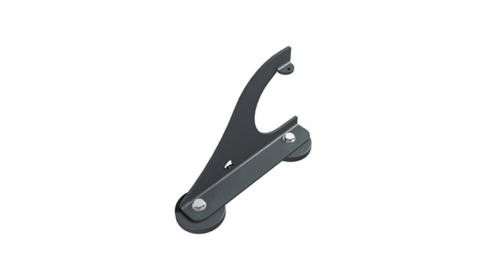
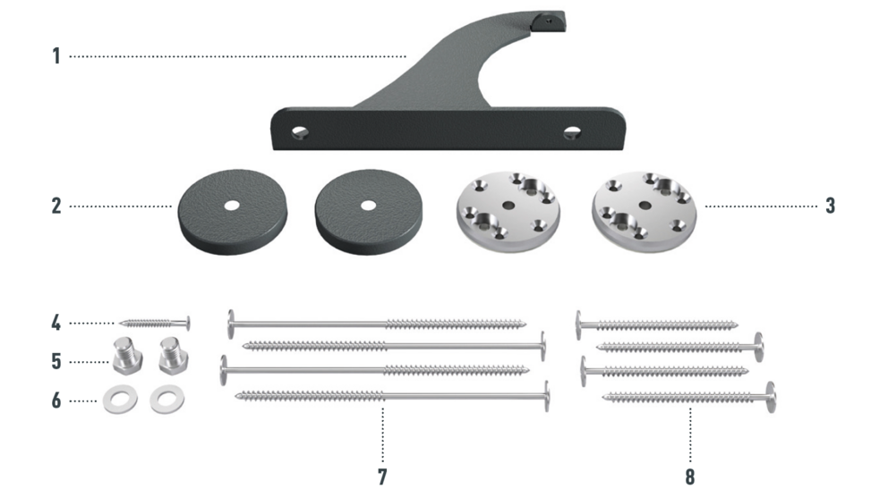
Snow guards are respectively pushed up into the central plate punching and fastened with at least 2 grooved nails. The number of clips in panels is not influenced by the use of snow guards.
With roof tiles, 2, 4 or 8 snow guards are installed per m² (see table below - Installation patterns DP1, DP2 and DP3). The first two rows must be equipped with snow guards throughout.
Snow guard installation patterns for roof tile


Snow guards are respectively pushed up into the left of the two central plate punchings and fastened with at least 2 grooved nails. The number of clips in the shingles is not affected by the use of snow guards.
With roof shingles, 2.5, 5 or 10 snow guards are installed per m² (see table below - Installation patterns DS1, DS2 and DS3). The first two rows must be equipped with snow guards throughout.
Snow guard installation patterns for shingle


Snow guards are respectively pushed up into the left of the two DS.19 shingle central plate punchings (marked “ST”) and fastened with at least 2 grooved nails. With a DS.19, the number of clips is not influenced by the use of snow guards.
With DS.19 shingles, 2, 4 or 8 snow guards are installed per m² (see table below - Installation patterns DS.19 1, DS.19 2 and DS.19 3). The first two rows must be equipped with snow guards throughout.
Snow guard installation patterns for DS.19 shingle


Snow guards are respectively pushed up into the centre of the punching in the rhomboid roof tiles 29 × 29 and fastened with at least 2 grooved nails. If a snow guard is mounted, no additional clip attachment is required on this rhomboid roof tile 29 × 29.
With rhomboid roof tiles 29 × 29, 3, 6 or 12 snow guards are installed per m² (see table below - Installation patterns DR1, DR2 and DR3). The first two rows must be equipped with snow guards throughout.
Snow guard installation patterns for rhomboid roof tile 29 × 29


Snow guards are respectively pushed up into the centre of the punching in the rhomboid roof tiles 44 × 44 and fastened with at least 2 grooved nails. The number of fastenings in the rhomboid roof tiles 44 × 44 is not affected by the use of snow guards. With rhomboid roof tiles 44 × 44, 1.3, 2.6 or 5.2 snow guards are installed per m² (see table below - Installation patterns DR44 1, DR44 2 and DR44 3). The first two rows (starting plates for rhomboid roof tiles 44 × 44 and the first row of rhomboid roof tiles 44 × 44) must be equipped with snow guards throughout.
Snow guard installation patterns for rhomboid roof tile 44 × 44


Snow guards are pushed up on the curved embossing on the fold and fastened with at least 2 grooved nails. The number of fastenings in the R.16 roof tiles is not influenced by the use of snow guards.
With R.16 roof tiles, 1.7, 3.4 or 6.8 snow guards are installed per m² (see table below - Installation patterns R.16 1, R.16 2 and R.16 3). The first two rows must be equipped with snow guards throughout.
Snow guard installation patterns for R.16 roof tile


Snow guards are pushed up on the curved embossing on the fold and fastened with at least 2 grooved nails. The number of fastenings in the FX.12 roof panels is not affected by the use of snow guards.
With FX.12 roof panels, 1.7, 3.4 or 6.8 snow guards are installed per m² (see table below - Installation patterns FX.12 1, FX.12 2 and FX.12 3). The first two rows must be equipped with snow guards throughout.
Snow guard installation patterns for FX.12 roof panel


Special feature of joint offset with FX.12 roof panels
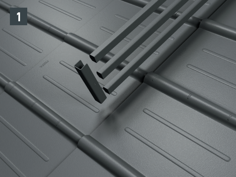
In principle, the FX.12 roof panels are laid at irregular intervals with an offset of the vertical angle fold of at least 220 mm. Due to any offset of the FX.12 roof panels, no symmetrical installation pattern is possible. If the use of snow guards is planned for FX.12, it is recommended to lay the FX.12 roof panels with a regular offset. This impairs the irregular appearance that can usually be achieved with FX.12 roof panels, however, a regular installation patterns is only possible with snow guards (Fig. 1 and 2).


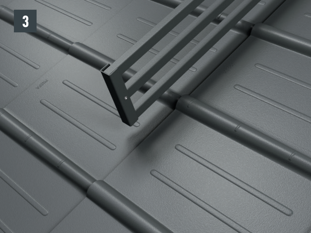
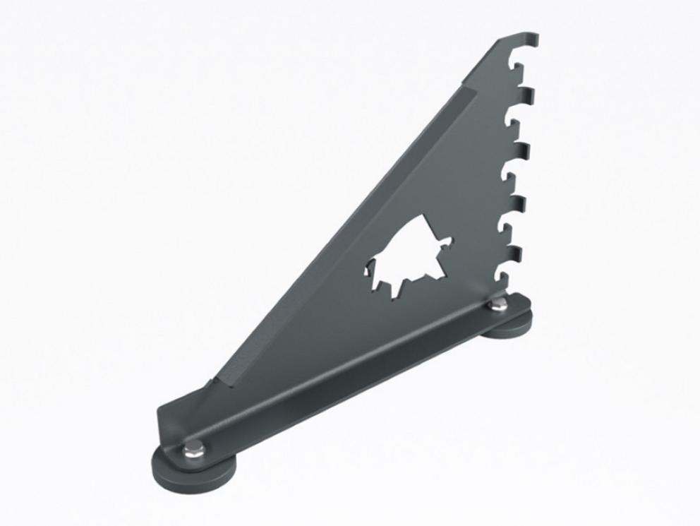
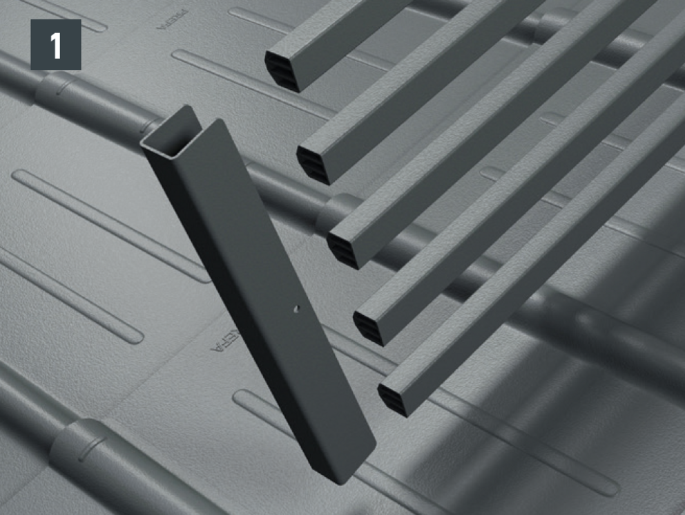
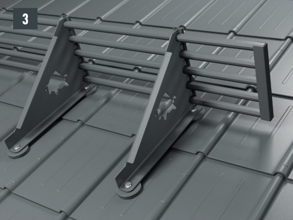
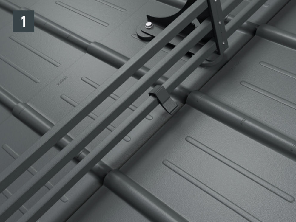
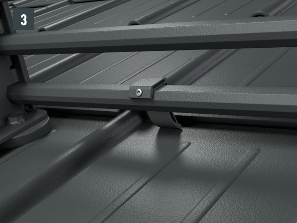
The snow rake brackets are installed with two foot parts on the roof membrane. The insert profiles are inserted into the snow rake hook and fastened with a fixing slider. The insert profiles are then connected to each other using sockets - Total height with foot parts: 219 mm.
The snow rake system can also be retrofitted.
Depending on the object and location, it may be necessary to mount several rows of snow rakes. The maximum permissible distances are to be calculated depending on the snow load, the roof pitch and the rafter distance.
Pipe-style snow guard system
Substrate |
The pipe-style snow guard system can only be installed on a solid, flat and fully supported substrate. |
|---|---|
Technical details |
Made of colour-coated, high-strength aluminium alloy, consisting of two foot parts with surface seal, snow rake hook and fixing slider, incl. fastening material. |
Dimensions |
Hook (H × W × D): 205 × 50 × 300 mm |
Note
With all PREFA roof systems, it may be necessary to fit a base plate (e.g. if there is a rebate or crest in the area of the rafters). Do not place and fasten foot sections on the fold or crest of the PREFA roof covering.
CAUTION: Observe installation areas of the PREFA roof systems.

1 Snow rake brackets |
6 2 13.0 washers |

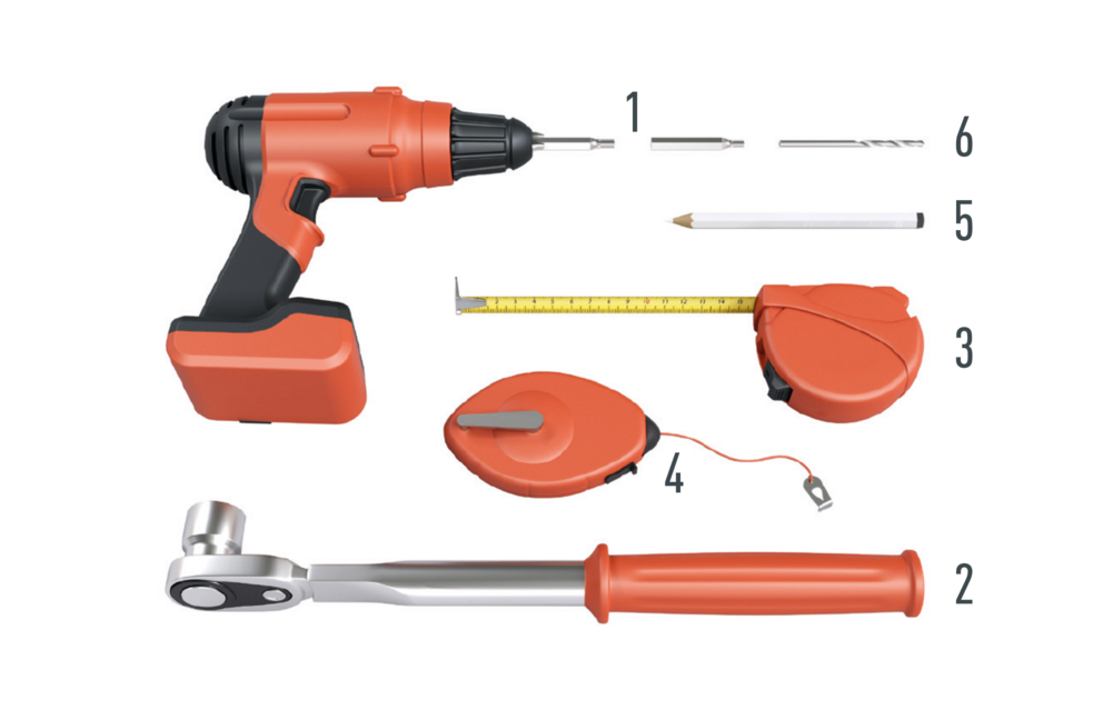
1 Drill with torx TX40 and TX25 |
4 Chalk line |


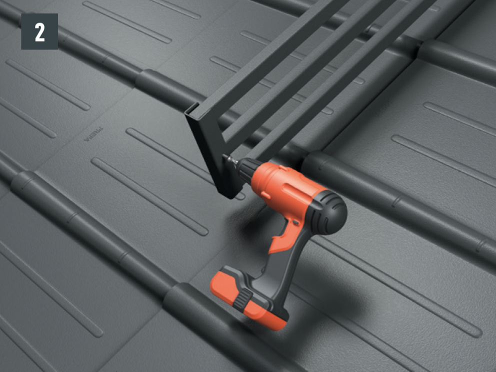
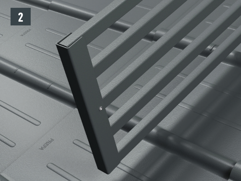
Mark the centre of the rafter. The upper foot part (outer edge) should have a distance of at least 10 mm to the overlying fold. Observe a distance of both foot parts of 145 mm (measured on the inside) (Fig. 1).
For attachment to the rafter, the drill holes (∅ 8.5 mm) must lie on the axis of the snow rake hook (course of the rafter) - Fixing screws in one axis with the rafter. Remove rear protective film on the foot parts, position and stick on (Fig. 2).
Note
Do not place and fasten foot sections on the fold or crest of the PREFA roof coverings. Observe mounting areas on the respective roof products. It may be necessary to fit a base plate (e.g. if there is a rebate or crest in the area of the rafters).


The XL snow rake brackets are installed with two foot parts in the rafter on the roof membrane. The insert profiles are inserted into the XL snow rake bracket and fastened with a fixing slider. The insert profiles are then connected to each other using sleeves – total height 360 mm.
The XL pipe-style snow guard system can also be retrofitted.
Depending on the object and location, it may be necessary to mount several rows of snow rakes. The maximum permissible distances are to be calculated depending on the snow load, the roof pitch and the rafter distance.
XL pipe-style snow guard system
Substrate |
The XL pipe-style snow guard system can only be installed on a solid, flat and fully supported substrate. |
|---|---|
Technical details |
Made of colour-coated, high-strength aluminum alloy, consisting of two foot parts with surface seal, XL snow rake bracket and fixing slider, incl. fixing material |
Dimensions |
Hook (H × W × D): 345 × 50 × 515 mm |
Note
With all PREFA roof systems, it may be necessary to fit a base plate (e.g. if there is a rebate or crest in the area of the rafters). Do not place and fasten foot section on the fold or crest of the PREFA roof covering.
CAUTION: Observe installation areas of the PREFA roof systems.

1 Snow rake brackets |
6 2 13.0 washers |

1 Drill with torx TX40 and TX25 |
4 Chalk line |


Note
Do not place and fasten foot section on the fold or crest of the PREFA roof covering. Observe mounting areas on the respective roof products. It may be necessary to fit a base plate (e.g. if there is a rebate or crest in the area of the rafters).


Attention
Only attach ice claws to the points where the roof covering rests on the roof surface.
Installation is carried out with two foot parts on the roof membrane. Round timber with Ø 140 mm can be inserted in the mountain snow guard brackets and fixed using the screws provided. Total height of the supports with foot parts: 219 mm. The mountain snow guard supports can also be retrofitted. Available in all colors for PREFA roof systems (small format).
Depending on the object and location, it may be necessary to mount several rows of mountain snow guards. The maximum permissible distances are to be calculated depending on the snow load, the roof pitch and the rafter distance.
Mountain snow guard
Substrate |
The mountain snow guard brackets can only be installed on a solid, flat and fully supported substrate. |
|---|---|
Technical details |
Made of colour-coated, high-strength aluminium alloy, consisting of two foot parts with surface seal, mountain snow guard brackets and fixing slider, incl. fastening material, excl. round timber. |
Dimensions |
Hook (H × W × D): 205 × 50 × 300 mm |
Note
With all PREFA roof systems, it may be necessary to fit a base plate (e.g. if there is a rebate or crest in the area of the rafters). Do not place and fasten foot sections on the fold or crest of the PREFA roof covering.
CAUTION: Observe installation areas of the PREFA roof systems.
1 mountain snow guard bracket |
5 2 hexagon head screws M12 × 1.5 × 16 |
1 Drill with torx TX40 and TX25 |
4 Chalk line |


Note
Do not place and fasten foot section on the fold or crest of the PREFA roof covering. It may be necessary to fit a base plate (e.g. if there is a rebate or crest in the area of the rafters).


Mounting of the mountain snow guard bracket with two hexagon head screws (M12) to the foot parts (SW19; torque: 35 Nm) for roof tiles (Fig. 6A), shingles (Fig. 6B), rhomboid roof tiles (Fig. 6C), R.16 and FX.12 (Fig. 6D).


Note
Ice and, under certain circumstances, snow can slide down between the round timber and the roof covering. If necessary, additional snow guards or individually manufactured ice stoppers can be attached (no PREFA standard product).
You can only download content from one product category. If you require content from multiple categories, please create a separate download for each product area.