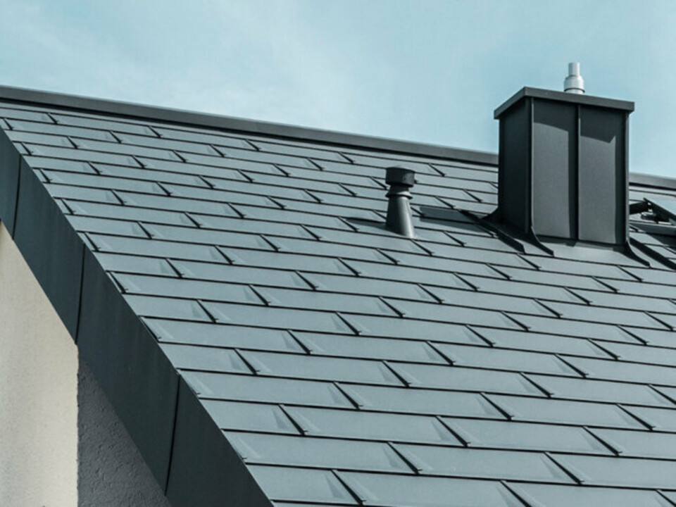
with PREFALZ in P.10 dark grey")


Click on the topic you want to go directly to the appropriate guide:
Chimney surroundings is carried out professionally and in the usual way as a tinsmith. Prepare the standing seam connections by bending up the PREFA roof covering (30 mm) for attaching the side paneling.
Front part

1 Return clip |
2 Apron flashing |
After installing the roof tile, the top panel fold is to be aligned in such a way that it is possible to hang a straight front part (Fig. 1-4).


Side parts

The length of the side part depend on the entire roof elements and fold allowances. At the lower end, hook in the side part in the roof tile.
In the upper area, the side part should protrude over the top panel cover.
For variant 1 - 150 mm
For variant 2 - 70 mm
Back flashing part
Variant 1


Variant 2


Tip
We highly recommend to mark all dimensions around the chimney properly
Front part

In preparation for the front part of the frame, end plates are to be laid for rhomboid roof tiles 29 × 29 or 44 × 44. These enable a horizontal hook-on seam for rainproof integration of the edging. Fasten each end plate for rhomboid roof tiles 29 × 29 with 1 patent clip and for rhomboid roof tiles 44 × 44 with 2 patent clips.
Special feature of rhomboid roof tile 29 × 29


When laying end plates for rhomboid roof tiles 29 × 29, the supplied cover strips are to be mounted above the rhomboid roof tile clip 29 × 29 (Fig. 1 and 2).
Side part
The length of the side part depend on the entire roof elements and fold allowances. At the lower end, hook in the side part in the PREFA roof covering. In the upper area, the side part should protrude over the top panel cover.

Mark the rhomboid roof tiles 29 × 29 and 44 × 44 depending on the width of the edging or depending on the required cut, add 30 mm for the lateral edging and trim the rhomboid roof tiles (Fig. 3). With each lateral upstand of the rhomboid roof tiles, the folds running diagonally downwards are to be cut out and bent up on the underside (Fig. 4-6).
Special feature of rhomboid roof tile 44 × 44


The sloping patent fold is to be notched at the top in the area of the raised edge corresponding to Fig. 6.


Back flashing part
Fold over the vertical folds of the side parts in the upper area (Fig. 10) and trim the back flashing part and the side parts with an allowance of 30 mm (Fig. 11). Make the fold - now starting plates for rhomboid roof tiles 29 × 29 or 44 × 44 can be mounted above the edging, and the covering of the roof surface can be continued.


Front part

Pull up shingle and DS.19 shingle until the last row of PREFA roof covering can be covered under the chimney.
Side parts


Note
With each left-hand upstand of the shingle and DS.19 shingle, the folds running diagonally downwards are to be notched in order to avoid any capillary action.


Only a professional installation guarantees a rainproof roof.


Prepare the surroundings (back and side part) and fix these to the side parts of the sub-structure framework with return clips (Fig. 10 and 11).
Back flashing part


Place the vertical folds of the side parts in the upper area and trim the back flashing part and the side parts with an allowance of 30 mm. Make the fold - now the covering of the roof surface above the surroundings can be continued (Fig. 12 and 13).
Front part
Pull up R.16 roof tile or FX.12 roof panel until the last row of PREFA roof covering can be covered under the chimney.
The length of the front part depends on the entire roof elements and fold allowances. At the lower end, hook in the front part in the PREFA roof covering.
Side part


Notch the upper patent fold in the area of the raised edge so that a hook fold remains, and bend the R.16 roof tile or the FX.12 roof panel upwards 30 mm at a right angle to the roof surface (Fig. 3 and 4).
Back flashing part


For the back flashing part, the upper hook-on seam of the R.16 roof tile or FX.12 roof panel to be covered is cut at approx. 200 mm and notched. The hook-on seam is bent backwards and the side overhang is bent up 90° (Fig. 5 and 6). The back part of the surroundings to be installed.


For standard single windows from Velux and Roto, PREFA offers prefabricated window surrounds for quick and precise installation.

Roof window edging
Technical details |
Colour-coated aluminium |
|---|
Note
The height of the lateral upstand is determined by the already prepared seams of the flashings. Therefore, attach the front and back parts to the roof window and mark the position of the upstand.
CAUTION: Below a roof pitch of 20°, the transverse seams and overlapping joints of the edging parts are to be additionally sealed.
During installation, observe PREFA’s installation instructions and the current professional standards and safety regulations.
Install the roof cover until the last row below the window.


After installing the roof tile in the desired position in the roof window surroundings, the top plate fold is to be aligned in such a way that it is possible to hang the front part of the PREFA roof window edging.


Abutment details


Notch the upper patent fold in the area of the raised edge so that a hook fold remains (Fig. 1 and 2), and bend the R.16 roof tile or the FX.12 roof panel upwards 30 mm at a right angle to the roof surface.
Back flashing part


With each left-hand upstand of the shingle and DS.19 shingle, the folds running diagonally downwards are to be notched in order to avoid any capillary action.


Only a professional installation guarantees a rainproof roof.
Apron flashing
In preparation for the front part of the roof window edging, end plates are to be laid for rhomboid roof tiles 29 × 29 or 44 × 44. These enable a horizontal hook-on seam for rainproof integration of the edging.

Abutment details
With each lateral upstand of the rhomboid roof tiles 29 × 29 and 44 × 44, the folds running diagonally downwards are to be cut out and bent up on the underside.


Only a professional installation guarantees a rainproof roof.
Back flashing part
In order to achieve a horizontal hook-on seam for rainproof integration of the edging behind the roof hatch, end plates must be laid for rhomboid roof tiles 29 × 29 or 44 × 44.
Now starting plates for rhomboid roof tiles 29 × 29 or 44 × 44 can be mounted above the edging, and the covering of the roof surface can be continued.


In order to allow for connection to the sub-roof or separation layer, the edging of the roof hatch is not pre-assembled on the wooden frame.
Note
Minimum roof pitch for roof hatches: 12°, the minimum roof pitch of the respective PREFA roof covering, must be observed.
CAUTION: The roof hatch is only suitable for ventilated roof spaces (unheated).
Install roof covering up to the desired position of the roof hatch.
CAUTION: Observe rafter layout.


After installing the roof tile in the desired position in the roof hatch, the top plate fold is to be aligned in such a way that it is possible to hang the front part of the roof hatch.


Abutment details


Notch the upper patent fold in the area of the raised edge so that a hook fold remains, and bend the R.16 roof tile or the FX.12 roof panel upwards 30 mm at a right angle to the roof surface (Fig. 1 and 2).
Back flashing part


With each left-hand upstand of the shingle and DS.19 shingle, the folds running diagonally downwards are to be notched in order to avoid any capillary action.


Only a professional installation guarantees a rainproof roof.
Apron flashing
In preparation for the front part of the frame, end plates are to be laid for rhomboid roof tiles 29 × 29 or 44 × 44. These enable a horizontal hook-on seam for rainproof integration of the edging.

Abutment details
With each lateral upstand of the rhomboid roof tiles 29 × 29 and 44 × 44, the folds running diagonally downwards are to be cut out and bent up on the underside (Fig. 1, 2, 3 and 4).


Back flashing part
In order to achieve a horizontal hook-on seam for rainproof integration of the edging behind the roof hatch, end plates must be laid for rhomboid roof tiles 29 × 29 or 44 × 44.
Now starting plates for rhomboid roof tiles 29 × 29 or 44 × 44 can be mounted above the edging, and the covering of the roof surface can be continued.

Base plate for rhomboid roof tile 29 × 29 (1), rhomboid roof tile 44 × 44 (2), R.16 roof tile and FX.12 roof panel (3) and DS.19 shingle (4) have the dimensions of the respective PREFA roof system and can be simply incorporated into the cover.
Note
Pay attention to the correct positioning of the pipe penetration through the substructure.
Furthermore, the penetration through or integration into various component layers (sub-roof, thermal insulation airtight layer ...) must be carried out professionally in accordance with national standards and regulations.

The base plate for roof tiles is in the form of a half plate with a conical edging socket folded in.


If the position of the penetration is specified and, due to this, the base plate cannot be used, pipe penetrations can be implemented using an base plate for folding in. Base plates are suitable for pipe penetrations from Ø 80–125 mm.
Depending on the roof system, the base plate extends over 1 to 2 rows and can be mounted at any point on the side.


Special feature of rhomboid roof panels

For the installation of a base plate, start and end plates must be laid with rhomboid roof tiles 29 × 29 or 44 × 44 (Fig. 1).
These enable a horizontal hook-on seam for rainproof integration of the edging plate.


As an alternative to base plate for welting in, a trim can also be folded into in a base plate and this can be covered in the roof covering. Connection to the roof covering is done with standing seams, analogous to the base plate for folding (Fig. 1 and 2).

If it is not possible to slide the base plate open due to the shape and circumstances of the penetration (e.g. satellite dish or antenna), two-piece universal vent pipe cover can be used. Integration in the roof covering is done with standing seams, analogous to the edging for folding.

In principle, continuous ventilation openings are to be preferred. If this is not possible in relation to the project, selective exhaust air openings (frog mouth hatches) can be used. They are placed in the appropriate number in the last row or covered along the ridges.
Please note that a large number of frog mouth hatches often have to be used in order to achieve the exhaust air cross-sections prescribed by the standards. Pay attention to the smooth or stucco design that matches the PREFA roof covering used. If installed on a fully boarded substrate, the boards must be cutted out sufficiently.
Air intake section of frog-mouth vent: ~ 30 cm²
Formwork and separation layer are to be cut out according to the ventilation cross-section (~10 cm in diameter). The roof covering is to be provided with a 1 cm high flare around the edges of the cut-outs.

1 rafters |
6 separation layer |
For the installation of pipes and cables, and for penetrations up to approx. 38.5 mm. The installation of pipes and cables and/or their integration into various component layers (sub-roof, thermal insulation, airtight layer, ...) must be carried out professionally in accordance with national standards and regulations.

Installing the c


Note
With all PREFA roof systems, it may be necessary to fit a base plate (e.g. if there is a rebate or crest in the installation area). Do not place and fasten solar hatch on the fold or crest of the PREFA roof covering.
Tip
Rubber parts that are subject to movement should be treated with the talc provided to improve sliding properties. To make it easier to put on the solar hatch, we recommend bending the corrugated pipe 90° in the direction of the eaves. Incl. grommets 1 × Ø 32–35 mm and 2 × Ø 10 mm.
A base plate can form the basis for the installation of snow rake systems, safety treads, roof safety hooks or other accessory products, e.g. if there is a rebate or crest in the area of the rafters. Do not place the respective accessory product on the fold or crest of the PREFA roof covering.

1 Pipe-style snow guard system |
4 separation layer |


Special feature of roof tiles
After installing the roof tile in the desired position in the base plate, the top plate fold is to be aligned in such a way that it is possible to hang the base plate.


Special feature of R.16 roof tile and FX.12 roof panel
Abutment details


Notch the upper patent fold in the area of the raised edge so that a hook fold remains, and bend the R.16 roof tile or the FX.12 roof panel upwards 30 mm at a right angle to the roof surface (Fig. 1 and 2).
Back flashing part


Special feature of shingle and DS.19 shingle
With each left-hand upstand of the shingle and DS.19 shingle, the folds running diagonally downwards are to be notched in order to avoid any capillary action.


Only a professional installation guarantees a rainproof roof.
Special feature of rhomboid roof tile 29 × 29 and rhomboid roof tile 44 × 44
Apron flashing
For the installation of a base plate, start and end plates must be laid with rhomboid roof tiles 29 × 29 or 44 × 44. These enable a horizontal hook-on seam for rainproof integration of the edging (Fig. 1).

Abutment details
With each lateral upstand of the rhomboid roof tiles 29 × 29 and 44 × 44, the folds running diagonally downwards are to be cut out and bent up on the underside.


Only a professional installation guarantees a rainproof roof.
Back flashing part


You can only download content from one product category. If you require content from multiple categories, please create a separate download for each product area.