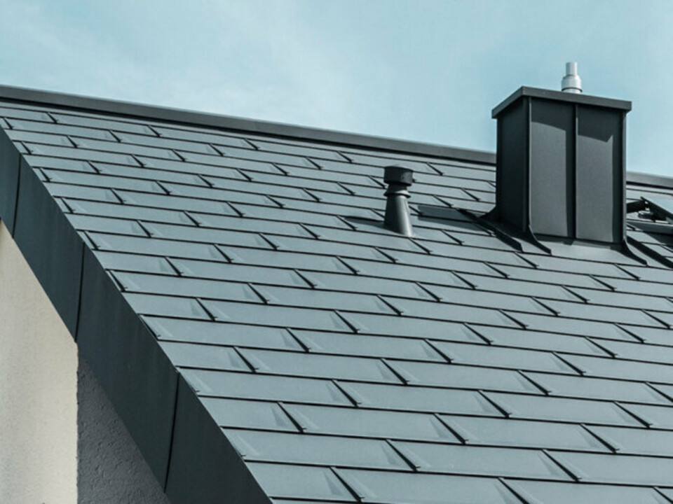
Installation guidelines
Please select one or more chapters to download.
Table of contents

Installation downpipe bracket

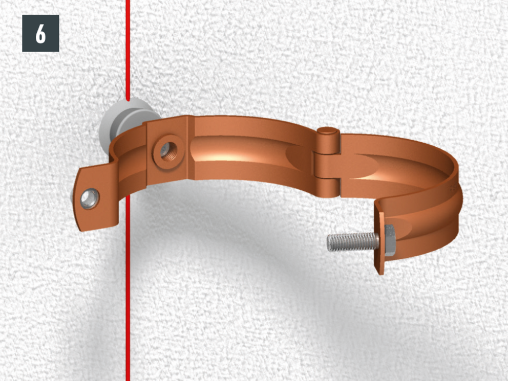
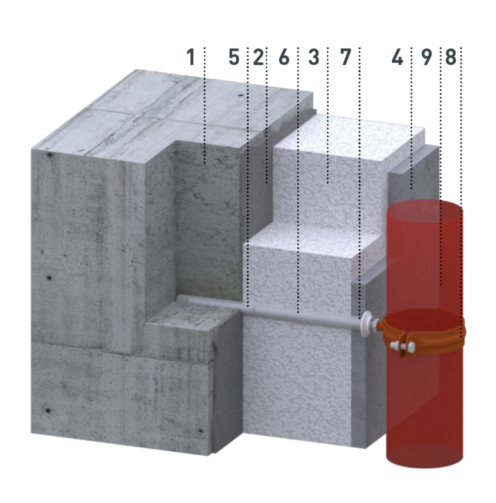
The downpipes are installed with pipe brackets. Suitable fasteners for the pipe brackets must be selected according to the substructure (façade surface).

Downpipe brackets should be installed with a minimum spacing of 20 mm between the bracket and façade. The distance between the pipe brackets should not be more than 2 m. (Observe national regulations and guidelines. Due to the length of the PREFA downpipes of 3 m, a maximum distance of 2 m has proven to be practical.)

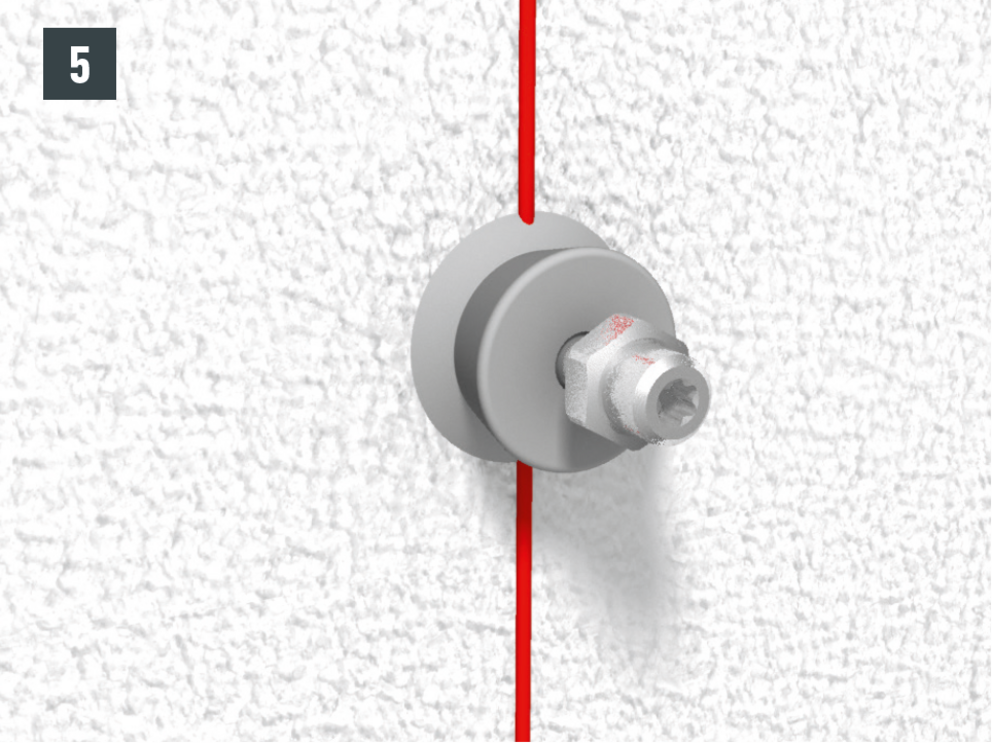
Cover caps for pipe bracket bolts can fulfill the following functions:

  • Covering worn pipe bracket holes.
  • Attaching a drip edge in case water runs along the bolt.

Note

If necessary, the cover caps must be sealed towards the façade (e.g. special silicone or special adhesive under the cover cap) in order to protect against driving rain.

Pipe bracket bolts for ETICS

For use with ETICS façades that have not yet been completed (available for insulation thicknesses of 100 - 180 mm and 180 - 260 mm).

  • Determine and mark the position of the pipe bracket support. Observe the vertical and flush execution (Fig. 1).
  • Pre-drill the marked points (drill Ø 8 mm) (Fig. 2).

Note

Observe the minimum distance to load-bearing external corners and reveals (at least 100 mm).

  • Drive in the dowel completely (Fig. 3).
  • Adjust the pipe bracket support to the appropriate insulation thickness and fix it with the rivet supplied (Ø 4 mm) (Fig. 4).
  • Mount the pipe bracket support with the supplied screws (Torx TX 25) (Fig. 5).
  • Slide the cover cap onto the fully mounted pipe bracket support and screw the counter nut onto the threaded mandrel (Fig. 6).
  • Screw the pipe clamp with M10 thread to the pipe clamp support. The distance from the pipe to the finished façade surface must be at least 20 mm (Fig. 7).
  • Completely install pipe bracket on ETICS (Fig. 8).

1 Supporting structure
2 Thermal insulation composite system (ETICS)
3 Rivet
4 Downpipe bracket
5 M10 thread

6 Cover cap
7 Counter nut
8 Pipe clamp with M10 thread
9 Downpipe
10 External plaster

Pipe bracket dowel

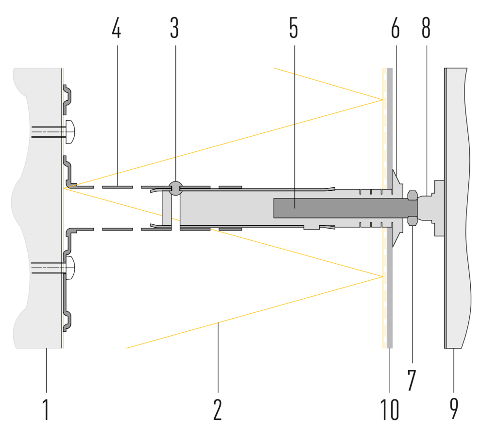
For use with existing ETICS façades (insulation thickness 50 - 200 mm possible, min. anchorage depth in the masonry: 70 mm).

  • Determine and mark the position of the pipe bracket dowel. Observe the vertical and flush execution. Observe the minimum distance to load-bearing external corners and reveals. In corner areas (e.g. wall corner), the dowel should be pressed in so that the expansion acts parallel to the edge (Fig. 1).
  • Pre-drill the marked position with a Ø 10 mm drill according to the length of the pipe bracket dowel. Minimum anchoring depth in the masonry: 70 mm (Fig. 2).
  • Drive in the pipe bracket dowel until it is flush with the façade (Fig. 3).
  • Push the cover cap onto the pipe bracket bolt and glue it to the façade with a special adhesive so that it is protected against driving rain (Fig. 4).
  • Screw the pipe bracket bolt into the pipe bracket dowel (with Torx TX 25 or SW13) (Fig. 5).
  • Screw the pipe bracket or square downpipe retaining clamp onto the PREFA pipe bracket bolt (Fig. 6).

Note

The distance between the PREFA downpipe and the façade surface must be at least 20 mm. When using the square downpipe, observe a distance of at least 45 mm between the wall and the square downpipe.

1 Masonry
2 Adhesive
3 Insulation
4 Plaster
5 Pipe bracket bolt

6 Pipe bracket dowel
7 Cover cap
8 Downpipe bracket
9 Downpipe

Wall mounting plate

For use on metallic façades and substructures (aluminium composite panels, trapezoidal façades and shaped pipes).

Note

Fastening material is not included in the scope of delivery. Use screws or rivets corresponding to the substructure.

Pipe bracket bolt

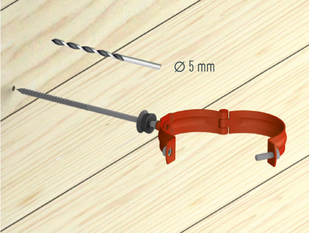
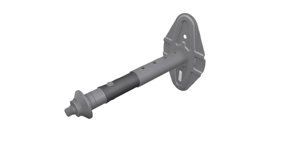
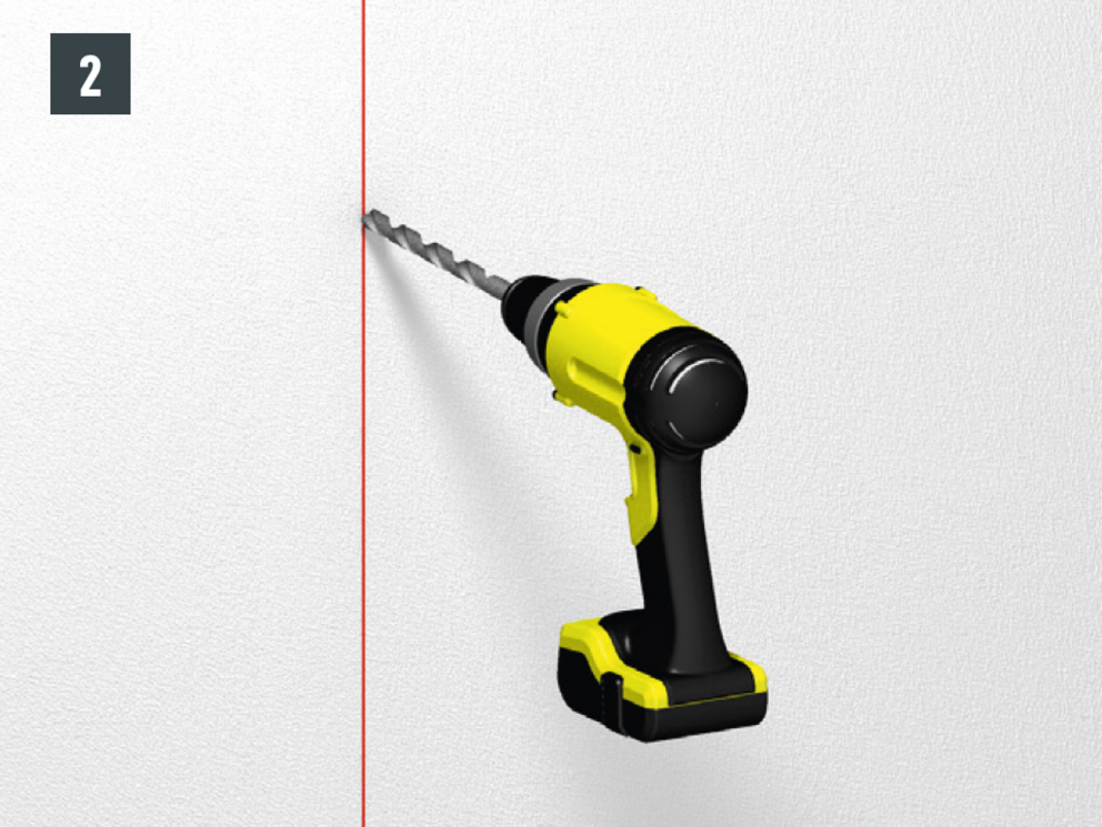
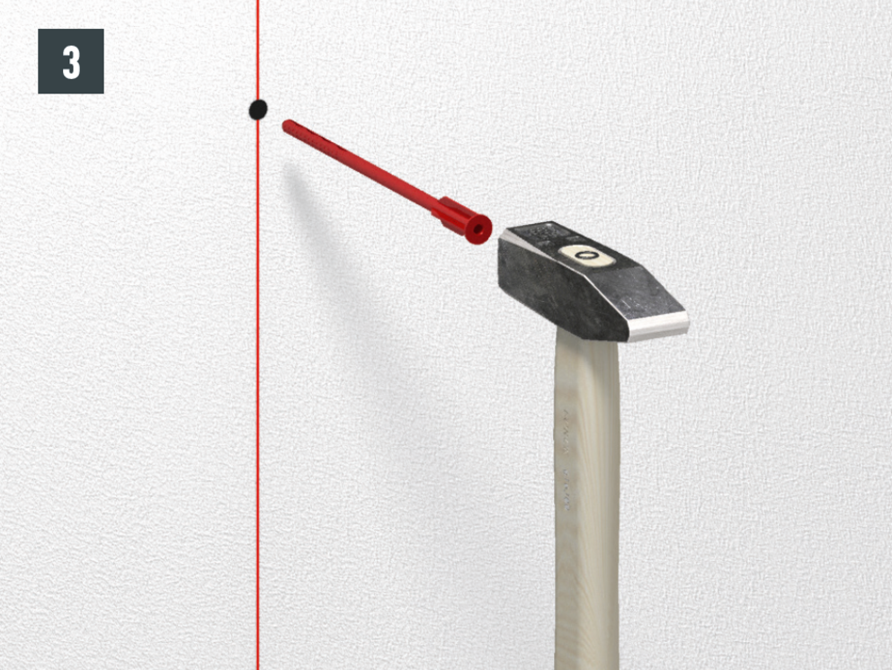
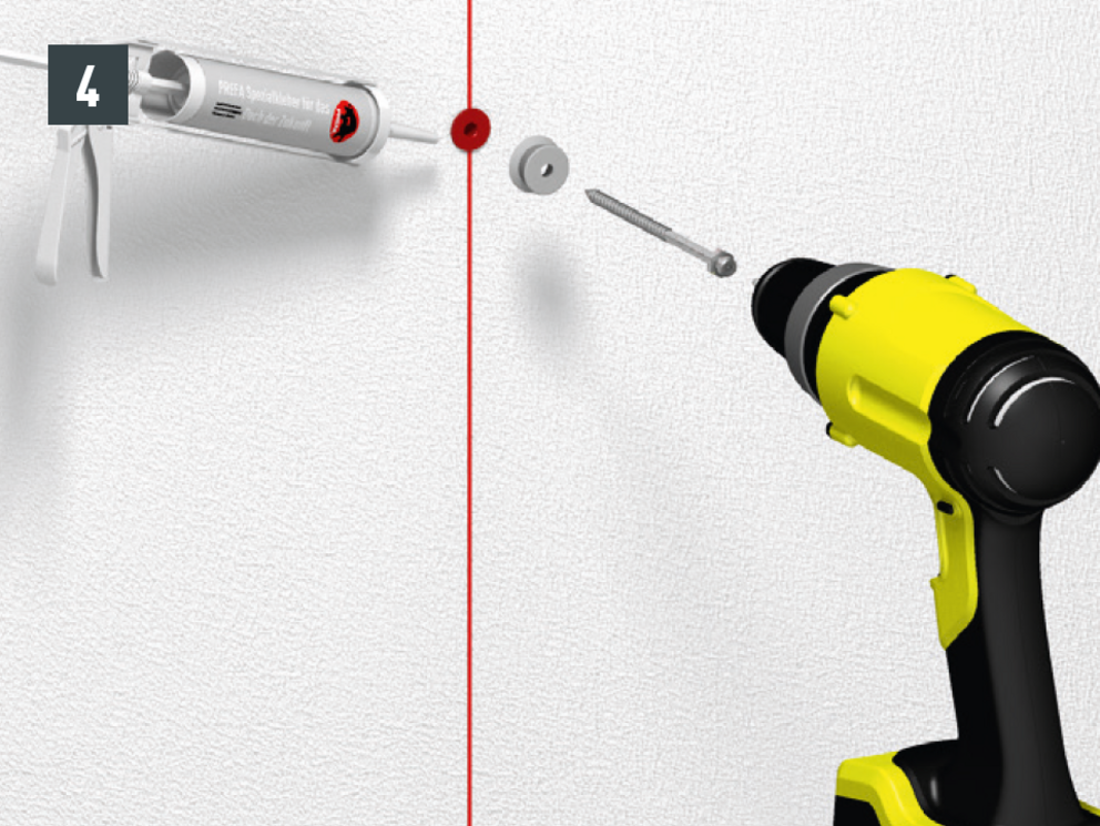
For use in concrete, brick and wood. Mandrel length 140/200/330 mm. Mark, pre-drill Ø 5 mm, pull on the cover cap and screw in with a TX 25. 

If necessary, the cover caps must be sealed towards the façade (e.g. special silicone or special adhesive under the cover cap) in order to protect against driving rain.

Note

Take special care when pre-drilling sand-bound substructures.

Leader head

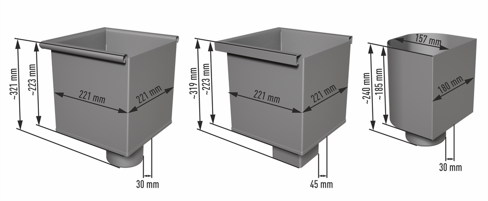
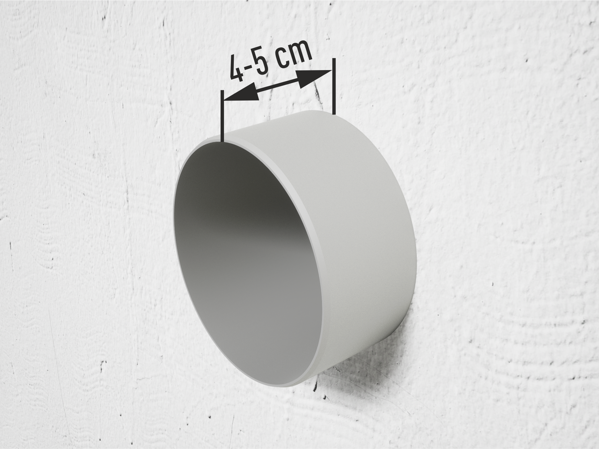
Leader heads are to be mounted on the façade with suitable fasteners, which are to be adapted to the respective substructure. 

Installing the seal prevents any water from escaping at the rear of the leader head.

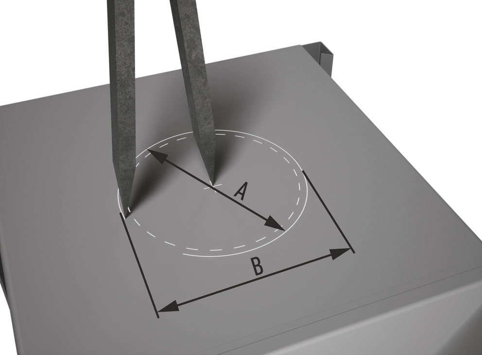
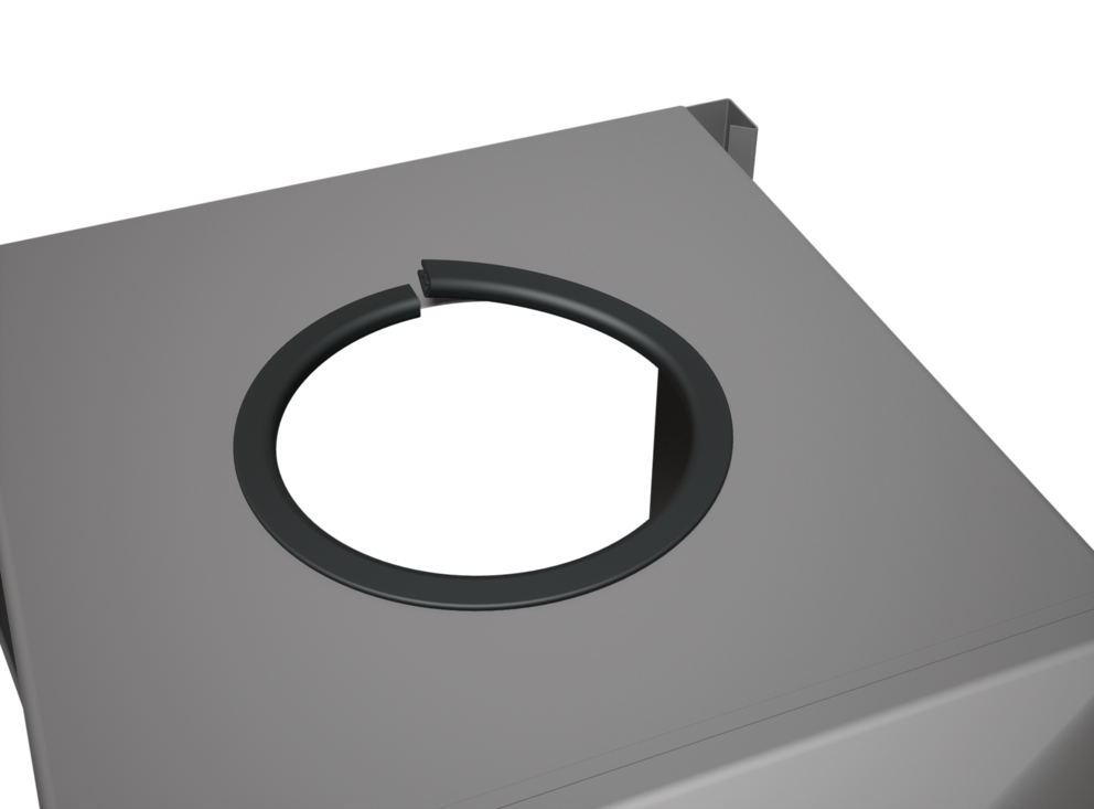
  • Mark and cut out pipe diameter including allowance for the seal on the back of leader head (Fig. 1).

    Allowance for the seal:
    — Diameter: 8 mm
    — Radius: 4 mm

  • Push the provided seal onto the cutting edge, starting at the top of the leader head. The joint must be at the top. Then shorten the seal to the appropriate length (Fig. 2).

Note

Maximum diameter: 120 mm

  • Installed seal with connected pipe (Fig. 3).

Parapet outlet connector

Installation

  • Cut off studs at a distance of 4-5 cm from the finished façade and cleanly chamfer the cutting edge (Figure 1).
  • Slide the EPDM seal and press it against the facade (Figure 2).
  • Insert the parapet outlet connector at a 90° angle to the outlet and rotate in the direction of the outlet with rotational movements. If necessary, lubricate plugs with a lubricant to facilitate installation (Figure 3).
  • Fully assembled gutter end cap (Figure 4).

Downpipe installation

  • Measure the downpipe for the swan neck. Fasten the swan neck to the gutter outlet (Fig. 1).
  • Mount pipe brackets to the wall. At least 2 pipe brackets must be mounted for each individual pipe run. The distance between the pipe brackets must not be more than 2 m. The distance from the pipe to the finished façade surface must be at least 20 mm (Fig. 2).

PREFA water collector

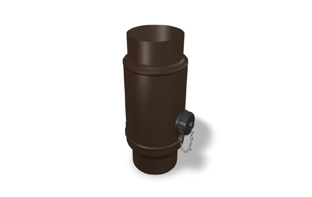
The rainwater collector is a practical tool for making the best use of natural resources! 

The rainwater collector fills the rain barrel with rainwater directly via the downpipe in the event of precipitation and collects the water up to the desired height.
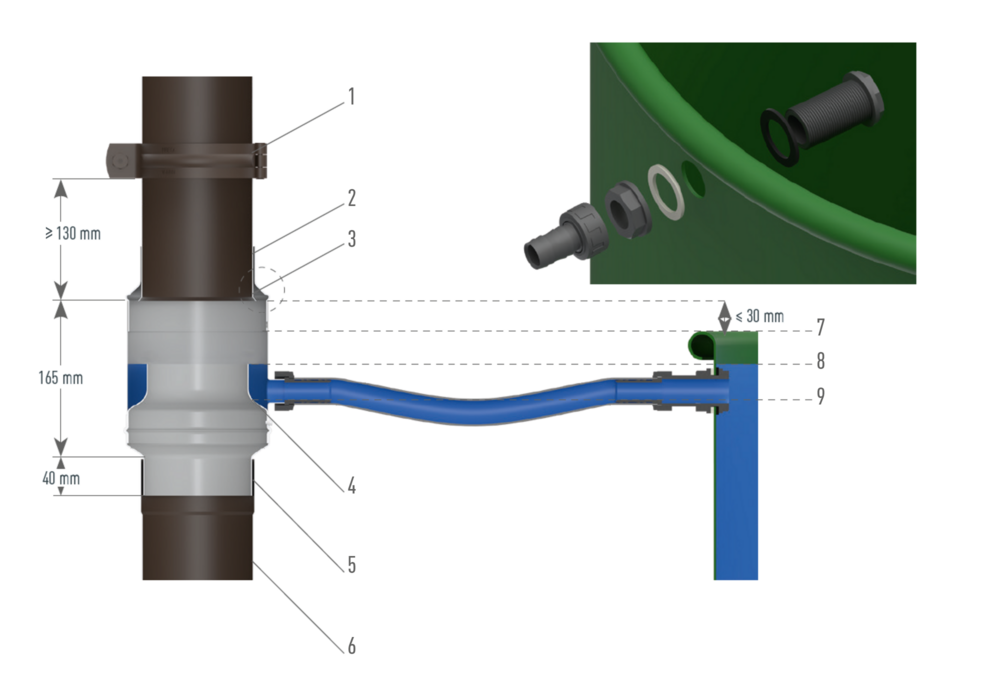
Installation of water collector

  • Decide on a horizontal and firm base for the rain barrel right next to the square downpipe.
  • Make a cutout of 165 mm in the downpipe. The top edge of the cutout is approx. 30 mm (or less) above the top edge of the rain barrel. The pipe bracket above should have a minimum distance of 130 mm from the cutout.
  • Put the detachable upper part on the upper downpipe and push it upwards. Then edge the upper downpipe edge outwards.
  • Widen the lower downpipe by 40 mm.
  • Lead the water collector up over the downpipe and then push it down into the widened downpipe.
  • Then push the detachable upper part back down onto the water collector. Do not fix the upper part of the collector, otherwise the collector cannot be removed for cleaning.
  • Mark the hole for the inlet opening of the barrel level with the hose opening in the water collector. Then drill the hole in the barrel (∅ 33 mm), and mount the hose connection in the rain barrel.

1 Downpipe bracket
2 Detachable upper part
3 Edging
4 Frost monitor
5 Extension

6 Downpipe
7 Minimum height of rain barrel
8 max. water level
9 Still water level

  • Connection to the rain barrel: 
    Screw the hose connection onto the water collector, then attach a standard 25 mm or 1” garden hose (not included in the scope of delivery).

Note

Depending on the degree of soiling, leaves, dirt and, if necessary, ice and snow should be removed from the water collector at regular intervals. In order to avoid damage from frost, the hose connection should be removed in winter and the water collector closed with the screw closure supplied.