with PREFALZ in P.10 dark grey")


Note
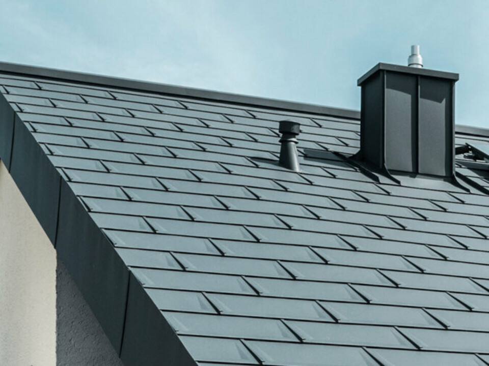
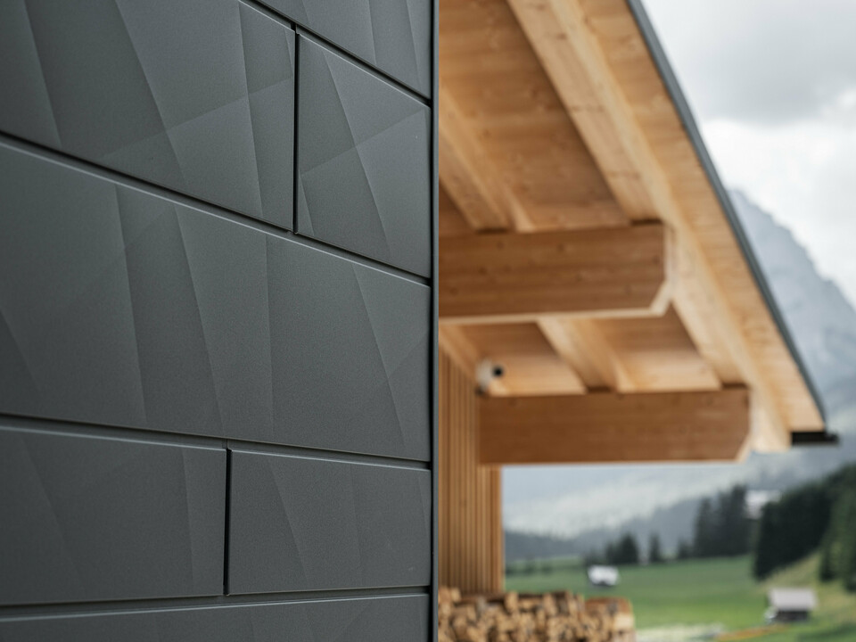
For standing seam coverings on façades, we recommend a maximum cut width of the aluminium strips of 500 mm. The narrower strip width helps to meet the special visual appearance and flatness requirements specific to façade claddings. Nevertheless, the properties typical of thin sheet metal (waviness, reflection, stresses, etc.) must be taken into account and cannot be excluded.
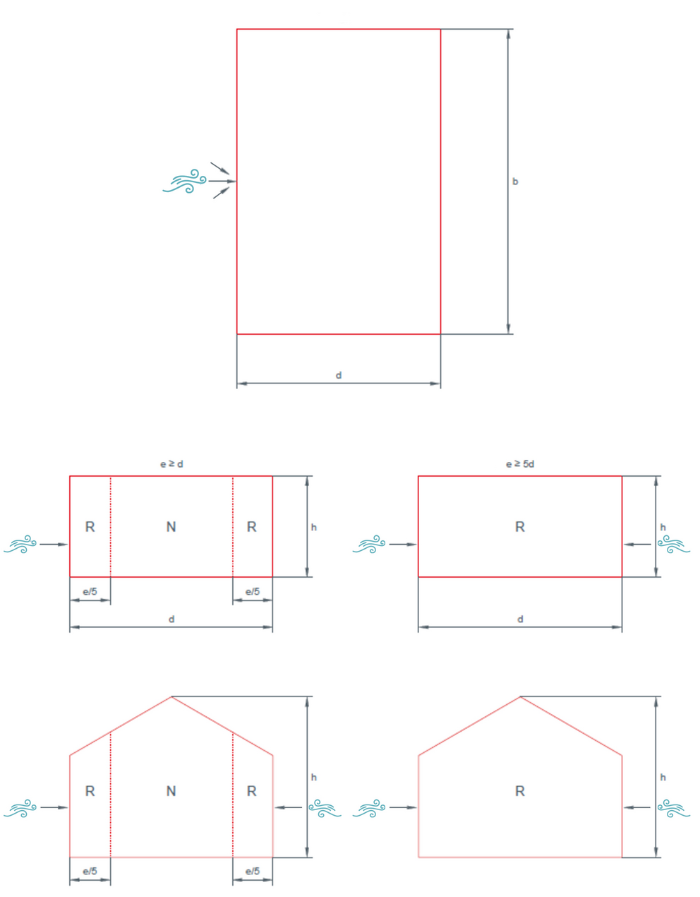
For standing seam applications observe local wind load conditions to determine tray width and spacing of clips. PREFA has prepared simplified dimensioning tables for professional installers. The simplified dimensions only apply to closed structures and only for PREFALZ or FALZONAL in combination with PREFA fixed and sliding clips and associated fasteners (nails/screws) from PREFA and when installing on full formwork with a bituminous separation layer. The tables are created based on EN 1991-1-4. Please refer to EN 1991-1-4 for the terrain category and to national supplements to EN 1991-1-4 for the base speed. The façade areas have been optimised to two areas and renamed (R = edge area, N = main area). The wind loads are higher at the edges of buildings and require special attention.
Building height: Greatest height of the building (e.g. ridge, hip)
The panel width is calculated from coil width minus seam loss:
Note
For assistance with calculations for objects in exposed locations, please contact the PREFA Product Technology Department at office.uk@prefa.com.


Comment
e = b or 2*h (whichever is smaller) – distance refers to the base area
b = dimension transverse to the wind
h = greatest building height
Note
The tables below are not applicable due to different national regulations for Germany and Switzerland. For further information, please contact the Product Technology department of the respective country!
The maximum panel width we recommend for façade installation also allows installation with this width in edge areas of objects with high wind loads. The table below describes this particular feature.
Specification of the maximum recommended tray width [cm] depending on the terrain category, building height and basic wind speed. The values given in the table are empirical values. The specified panel widths do not take into account waste when using standard coil dimensions.
Terrain category II
Basic speed pressure [kN/m²] |
Basic speed [m/sec] |
Building height < 15 [m] |
Building height 15-30 [m] |
Building height 30-50 [m] |
N | R [pcs./m²] |
N | R [pcs./m²] |
N | R [pcs./m²] |
||
≤ 0.32 |
≤ 22.5 |
43 | 43 |
43 | 43 |
43 | 43 |
≤ 0.39 |
≤ 25.0 |
43 | 43 |
43 | 43 |
43 | 43 |
≤ 0.47 |
≤ 27.5 |
43 | 43 |
43 | 43 |
43 | 43 |
≤ 0.56 |
≤ 30.0 |
43 | 43 |
43 | 43 |
43 | 43 |
Terrain category III
Basic speed pressure [kN/m²] |
Basic speed [m/sec] |
Building height < 15 [m] |
Building height 15-30 [m] |
Building height 30-50 [m] |
N | R [pcs./m²] |
N | R [pcs./m²] |
N | R [pcs./m²] |
||
≤ 0.32 |
≤ 22.5 |
43 | 43 |
43 | 43 |
43 | 43 |
≤ 0.39 |
≤ 25.0 |
43 | 43 |
43 | 43 |
43 | 43 |
≤ 0.47 |
≤ 27.5 |
43 | 43 |
43 | 43 |
43 | 43 |
≤ 0.56 |
≤ 30.0 |
43 | 43 |
43 | 43 |
43 | 43 |
Terrain category IV
Basic speed pressure [kN/m²] |
Basic speed [m/sec] |
Building height < 15 [m] |
Building height 15-30 [m] |
Building height 30-50 [m] |
N | R [pcs./m²] |
N | R [pcs./m²] |
N | R [pcs./m²] |
||
≤ 0.32 |
≤ 22.5 |
43 | 43 |
43 | 43 |
43 | 43 |
≤ 0.39 |
≤ 25.0 |
43 | 43 |
43 | 43 |
43 | 43 |
≤ 0.47 |
≤ 27.5 |
43 | 43 |
43 | 43 |
43 | 43 |
≤ 0.56 |
≤ 30.0 |
43 | 43 |
43 | 43 |
43 | 43 |
You can only download content from one product category. If you require content from multiple categories, please create a separate download for each product area.