with PREFALZ in P.10 dark grey")


Observe the minimum dimensions and angles that are technically possible as far as the material is concerned. Acute angles can be produced from an angular opening of 20°. If the angular opening is less than 20°, the tip of the angle must be finalised using a bar of at least 25 mm.

Note that cut-out letters, company logos, perforation patterns, etc. are only permitted on PREFABOND composite panels with an FR core. This type of machining is not permitted on panels with an A2 core.

Note
When processing the composite panels always make sure that you use suitable safety and personal protective equipment.
The following processing options are available:
Click on the processing option you want to go directly to the appropriate guide:
The PREFABOND aluminium composite panels can be processed using the following tools: a portable circular saw,
circular bench saw or vertical panel saw and a circular saw blade for metal. Diamond-tipped saw blades are also ideal for increasing service life. In order to protect the coated visible side, the panels should always be processed at the back. We highly recommend using a suction system to remove any chips.
Note
Make sure that the saw blade does not cause burring when cutting, as far as is possible. If this is not the case, the saw blade should be serviced (sharpened) or replaced if necessary.
Fixed and sliding points need to be prepared for the mechanical fastening of the composite panels. Drill the holes using a standard drill or a drill press, hole saw or circle cutter.
All cut-outs (e.g. cut-outs for lights or door handles) can be produced easily with a standard routing machine or jig saw. A guide template will help you to produce these cuts.
Note
PFEFA can produce complex cut-outs such as lettering and company logos with a CNC machine in the factory. The contours for this must be provided in a DWG or DXF file.
The V-groove milling technique can be used to produce reveal and corner constructions as internal or external corners. V-groove cutters with an opening angle of 90° and 135° can be used for this.


To prevent cracks from appearing on the coated visible side, when bending PREFABOND composite panels, the minimum material and ambient temperature must be 5 °C for panels with an FR core, and 20 °C for panels with an A2 core.
PREFA recommends that, especially for composite panels with an A2 core, V-groove cutting is only carried out with the aid of a CNC machine to ensure the correct milling depth.
If the panels are bent in low temperatures (≤ 15 °C), this can give the coating a haze-like appearance. Warm the panel to 20 °C or higher, and the haze-like appearance will disappear.
The V-groove required to make folds, whether for internal or external corners, should always be cut on the back of the panel. Correct V-groove cutting must be carried out in such a way that, on the one hand, 0.5 mm of the top layer (coated visible side) and, on the other hand, a further 0.2 to 0.4 mm (FR core) or a further 0.15 to 0.25 mm (A2 core) remain.
V-grooves with an opening angle of 90° or 135° are frequently used.
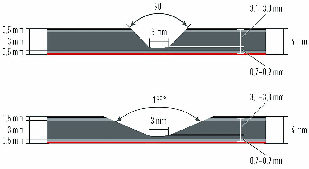
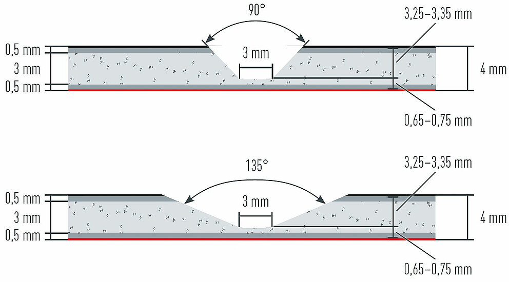
If the V-groove is too deep partially or over the entire length, it will not be possible to create an attractive fold with a constant radius. This could also cause the aluminium cover plate to crack on the visible side. However, if the V-groove is not sufficiently deep, folding will be very difficult. The V-groove folding axis should always be in the centre of the milled root face.


Make sure that, after folding, the composite panel always springs back slightly. In practice, this means that the bend must be folded a little more than desired so that the perfect dimensional accuracy is achieved after the panel springs back. The smallest possible side length of a termination is 20 mm.
Note
When determining how to correctly process the panel, make sure that you take the thickness of the adhesive system on the glued installation into account. Depending on whether it is an outer or an inner fold, add or subtract this thickness (usually, this is 3 mm) to or from the adhesive system specified by the adhesive manufacturer.

The examples shown below can be used as a guide. The illustrations show a mechanical fastening in each case.
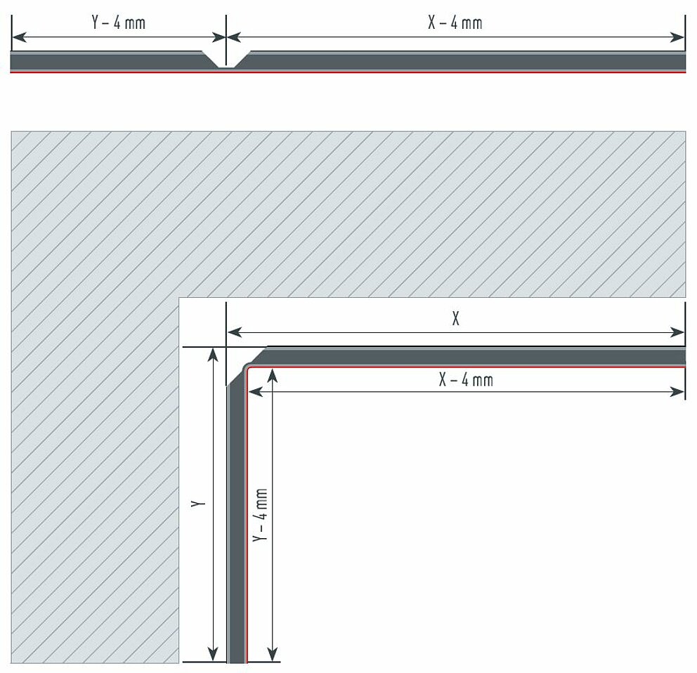
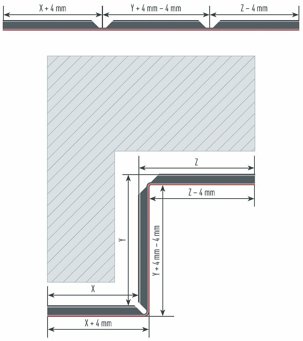
For an internal corner, the material thickness of the composite panel (4 mm) is deducted from the measured actual dimensions.
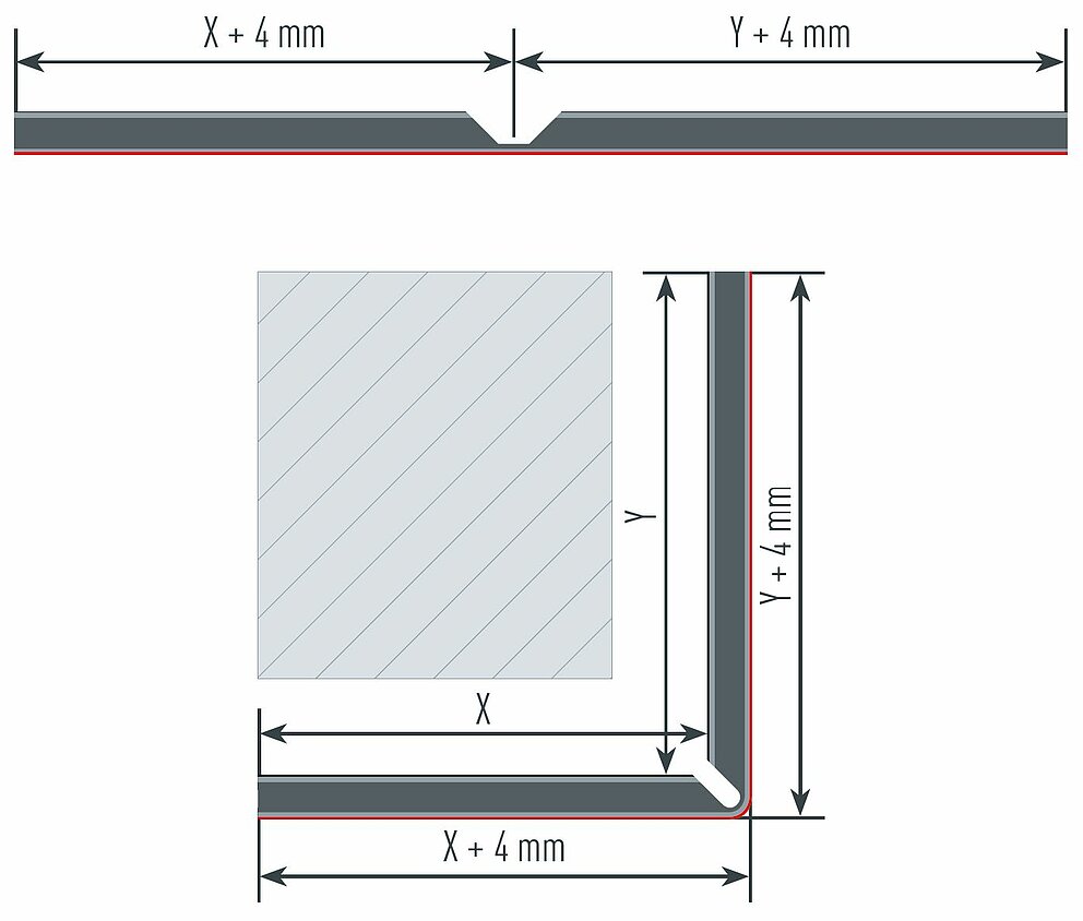
For an external corner, the material thickness of the composite panel (4 mm) is added to the actual measured dimensions.
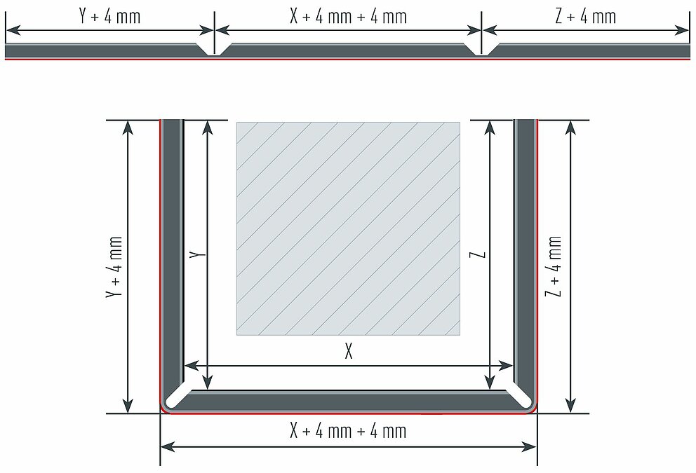
For a U-fold with two external corners, each corner is considered individually. To obtain the correct milling axis, the material thickness (4 mm) must be added to each side of the fold.
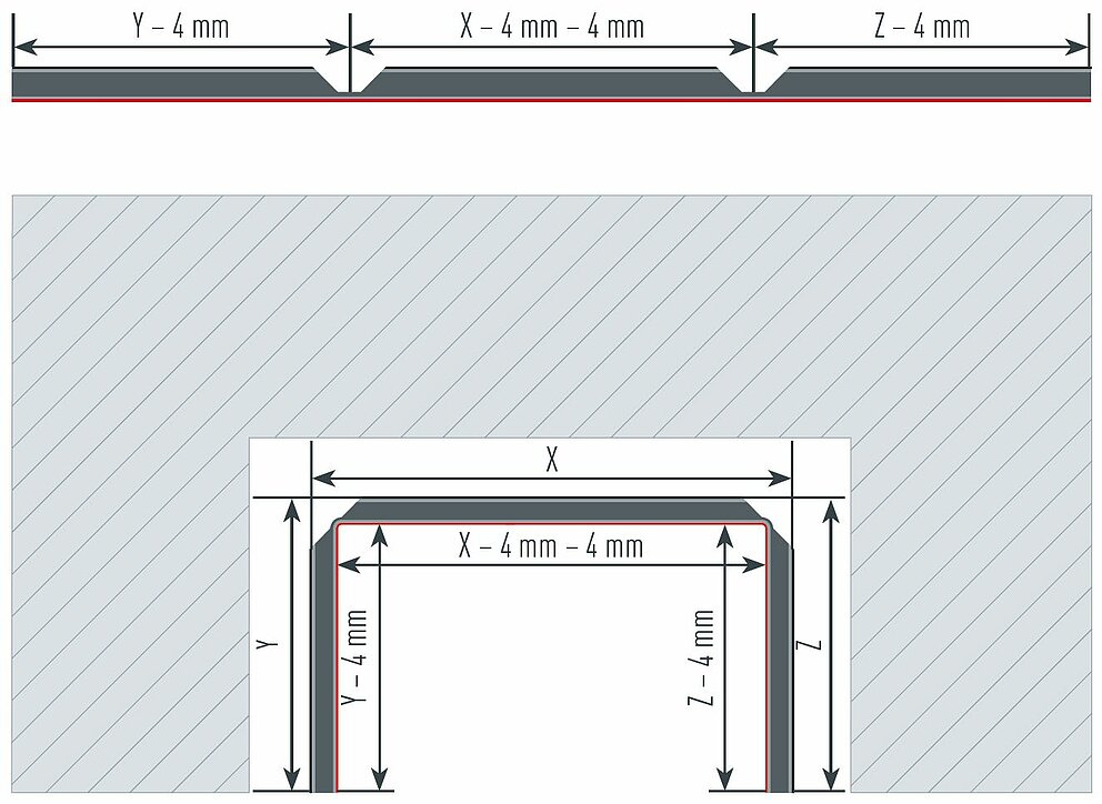
For a U-fold with two internal corners, each corner is considered individually. To obtain the correct milling axis, the material thickness (4 mm) must be deducted from each side of the fold.
On a Z-fold with one internal and one external corner, each corner is considered individually. To obtain the correct milling axis, on the internal corner, the material thickness (4 mm) must be deducted from each side of the fold, and on the external corner, the material thickness (4 mm) must be added to each side of the fold.
Perforated PREFABOND composite panels have a consistent hole pattern. Due to the mineral structure of the core, perforation with punching machines is not recommended for the PREFABOND with A2 core.
Perforation arrangement |
Hole diameter [w] |
Division [t] |
Open area [%] |
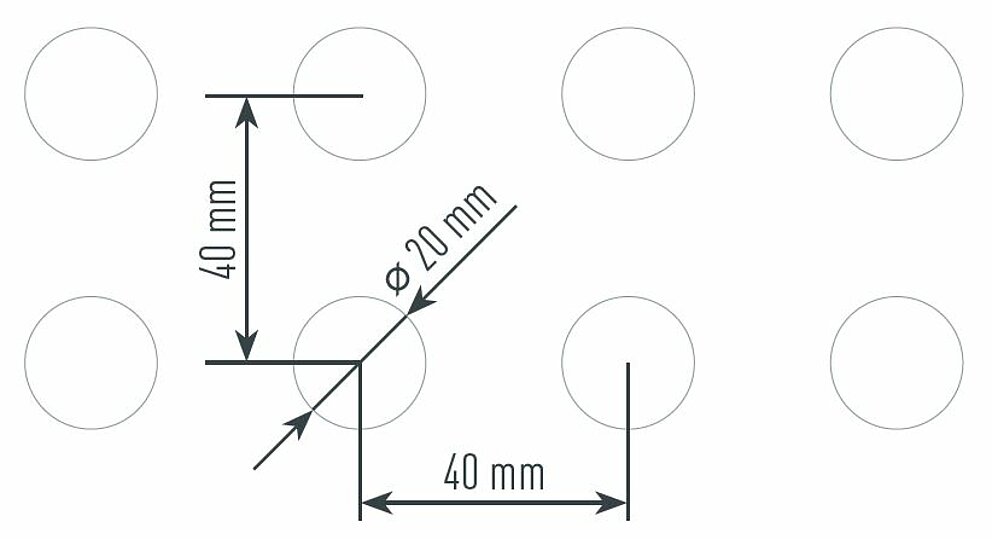
Round hole; square pitch |
20 mm |
40 mm |
19.6% |
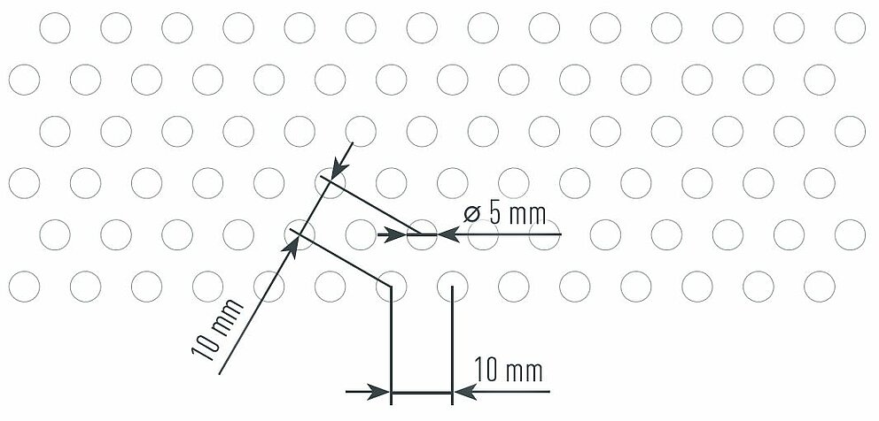
Round hole; staggered pitch |
5 mm |
10 mm |
22.6% |
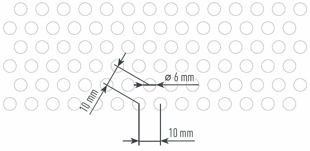
Round hole; staggered pitch |
6 mm |
10 mm |
32.6% |
Round hole; staggered pitch |
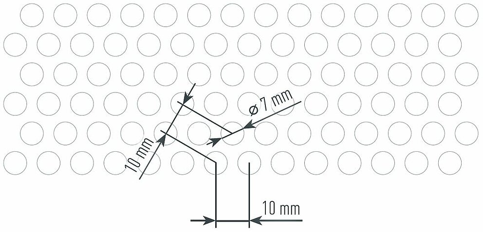
7 mm |
10 mm |
44.4% |
Round hole; staggered pitch |
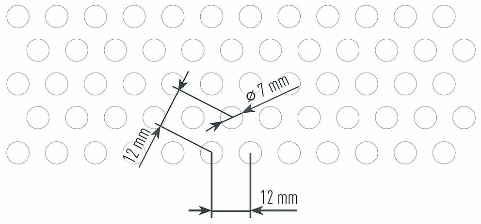
7 mm |
12 mm |
30.8% |
Round hole; staggered pitch |
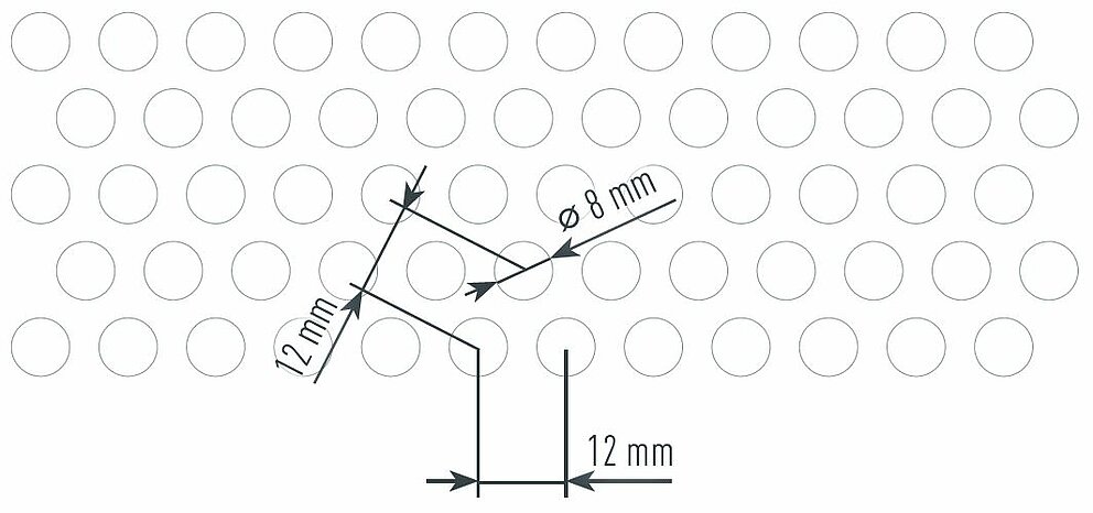
8 mm |
12 mm |
40.2% |
Round hole; staggered pitch |
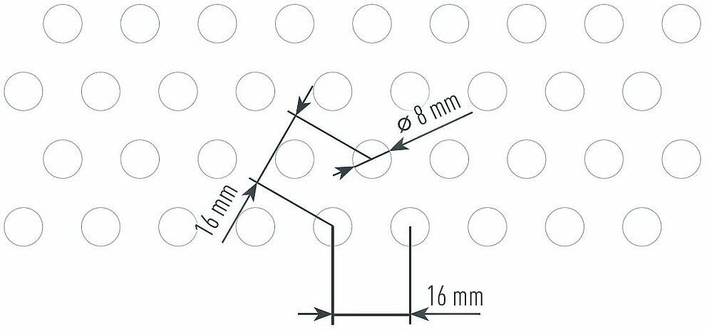
8 mm |
16 mm |
22.6% |
Round hole; staggered pitch |
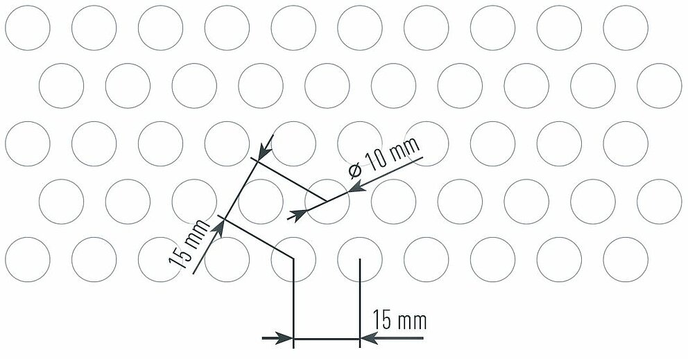
10 mm |
15 mm |
40.2% |
Round hole; staggered pitch |
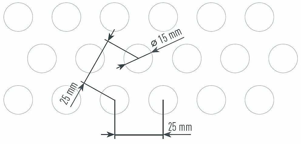
15 mm |
25 mm |
32.6% |
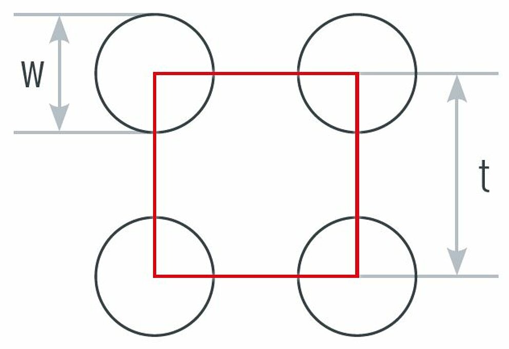
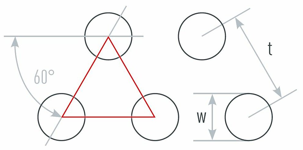
R = Round perforations
g = square pitch
v = staggered pitch
W = hole diameter
t = division
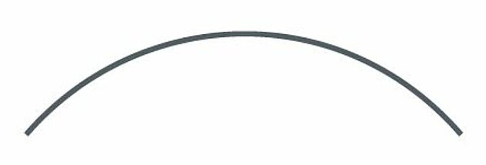
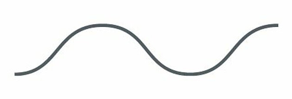
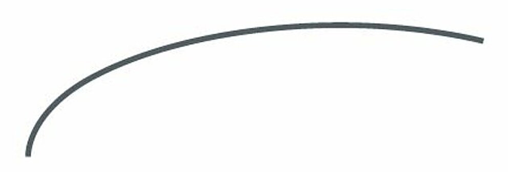
PREFABOND aluminium composite panels can be bent on three or four roll bending machines. PREFA advises against the use of a mechanical press brake.
PREFA offers a bending service for PREFABOND aluminium composite panels. In this case, please note the information provided below.

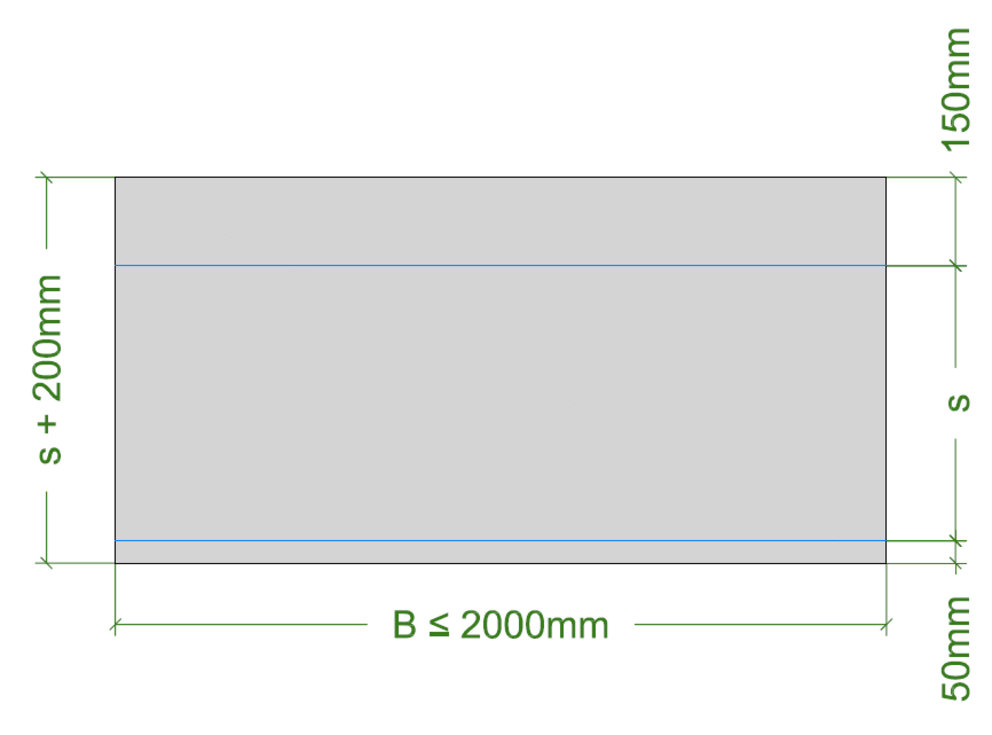
The roll bending process creates a small pressure mark on the panels which is trimmed by PREFA. Note the dimensions of the raw panel. At both ends, it is 200 mm larger in total than the radian measure actually required. 150 mm are added to the radian measure (s) at one end and 50 mm at the other end.

You can only download content from one product category. If you require content from multiple categories, please create a separate download for each product area.