with PREFALZ in P.10 dark grey")


Click on the topic you want to go directly to the appropriate guide:
Regardless of the panel size, at least 2 fixed points are required for the mechanical fastening of each panel. This is the only way to ensure that the panel is positioned stably and cannot twist.
Always use T-profiles with a support surface of at least 100 to 120 mm for the panel joint. L-profiles with a support surface of 40 mm are sufficientbetween the joints.
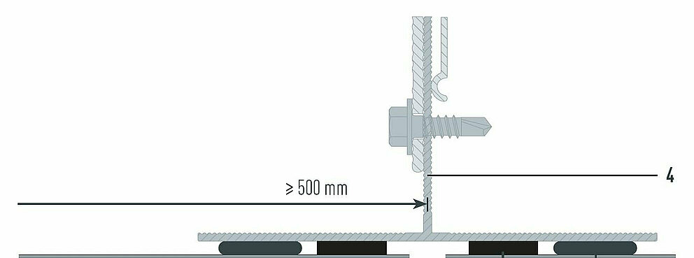
In order to take the expansion of the material into account, supporting rails must not be longer than 3,000 mm. Ensure that the substructure profiles are not joined in one panel, since a fixed connection is created here.
Fastening to 2 vertical support profiles

Fastening to 3 vertical support profiles

Fastening to at least 4 vertical support profiles

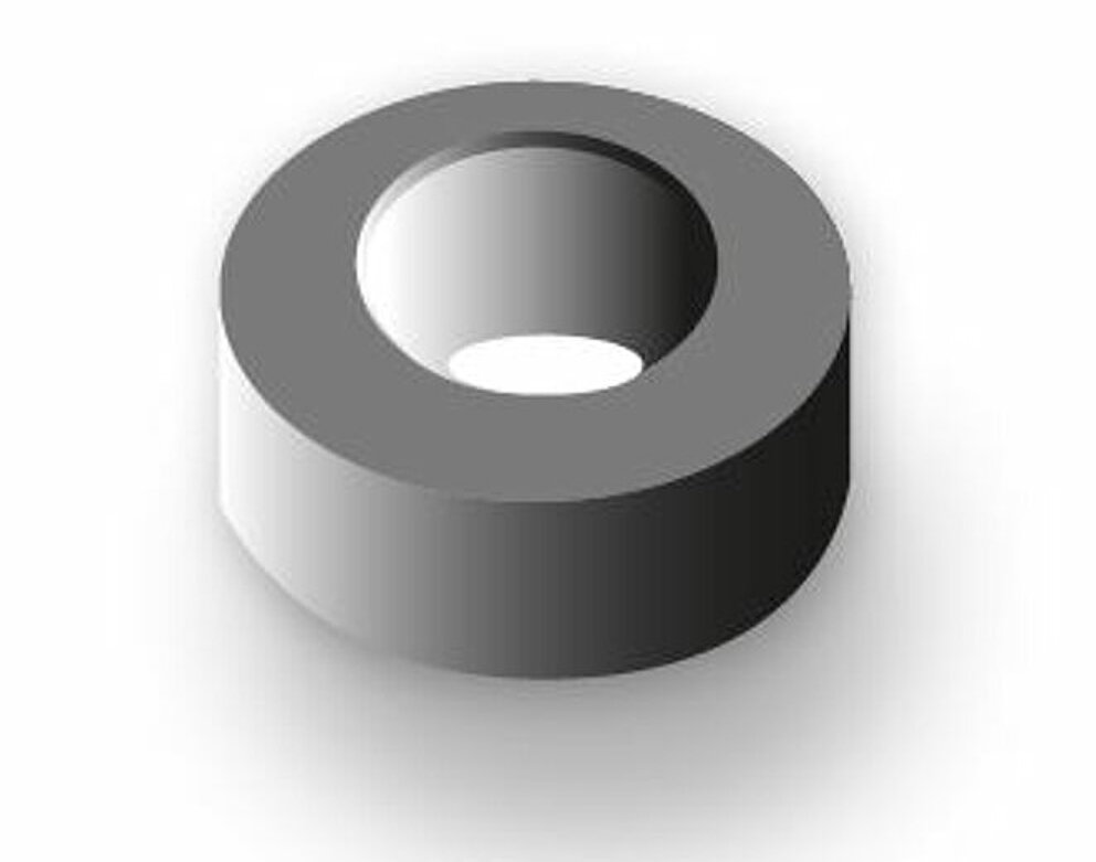
The riveted mechanical fastening system consists of a façade rivet and, if desired, a fixed point bushing.


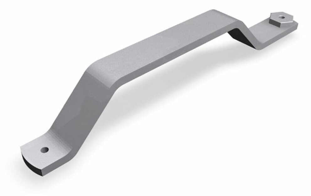
In order to achieve centric drilling of the substructure, only use either the appropriate bracket boring fixture or the spring-loaded boring fixture, which transfers the centre of the bore hole of a composite panel to the substructure.
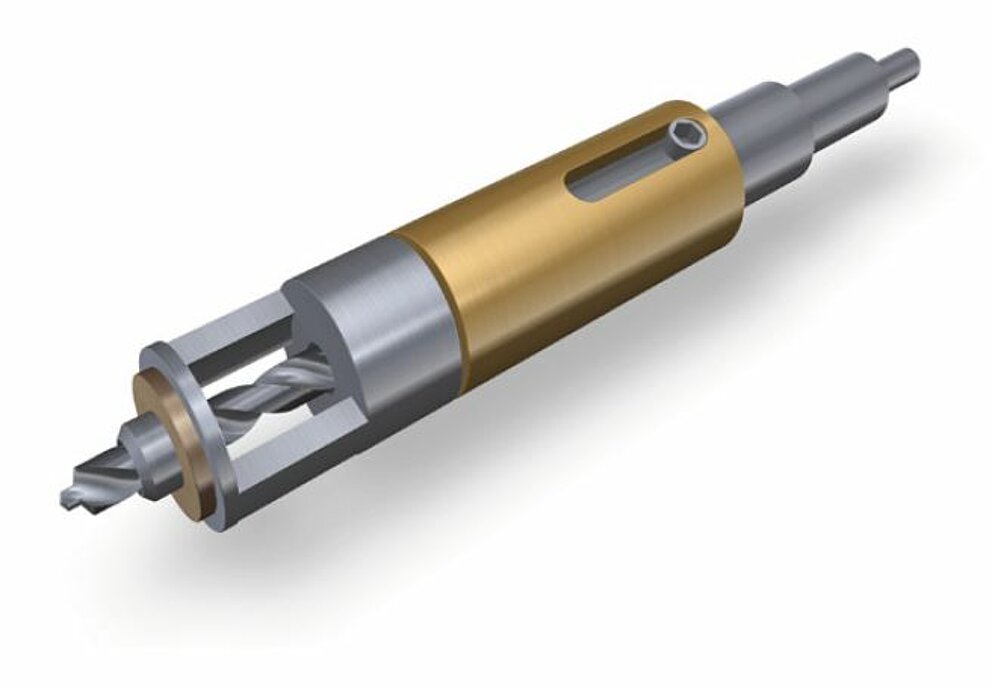
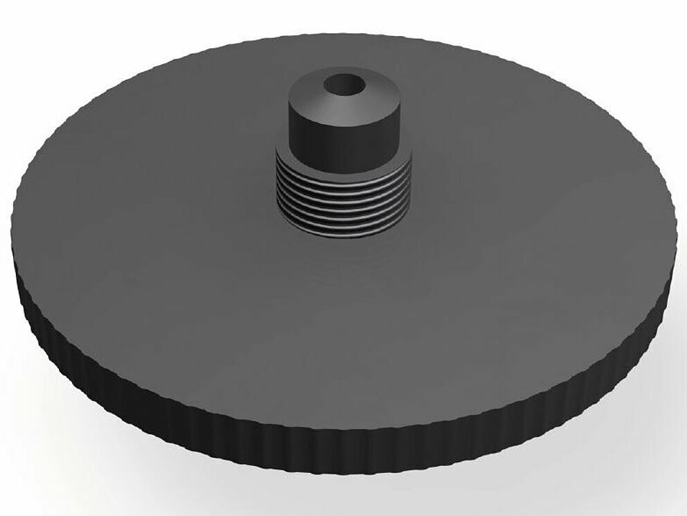
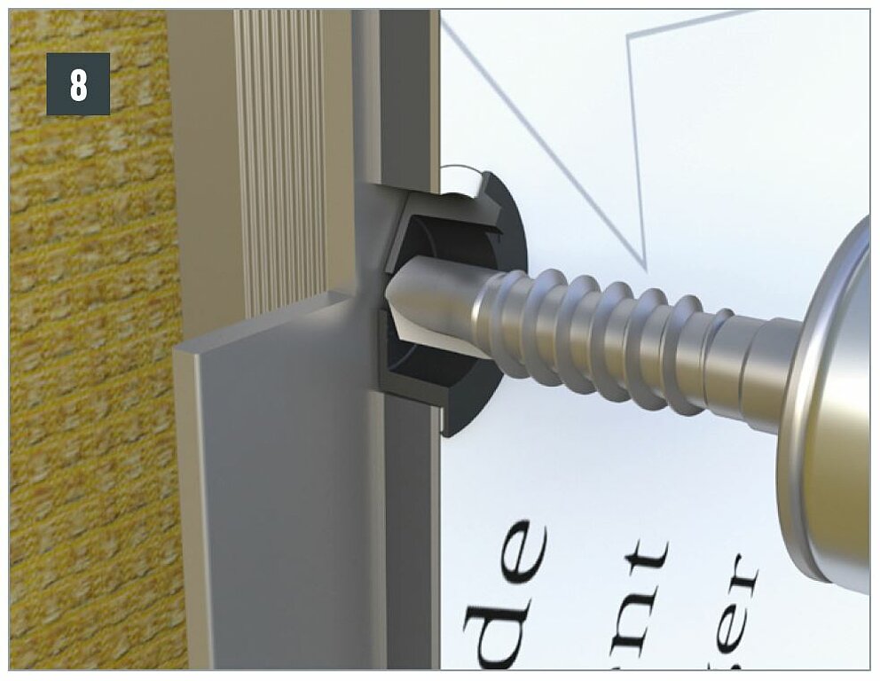
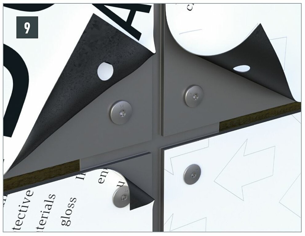
Use the PREFA film cutter (⌀ 5.1 mm and ⌀ 9.5 mm) to slightly score the protective film around the bore hole so that the protective film can be easily removed after the installation is complete. Otherwise, the film may become clamped between the panel and the bottom of the rivet head, making it difficult to remove.
Note
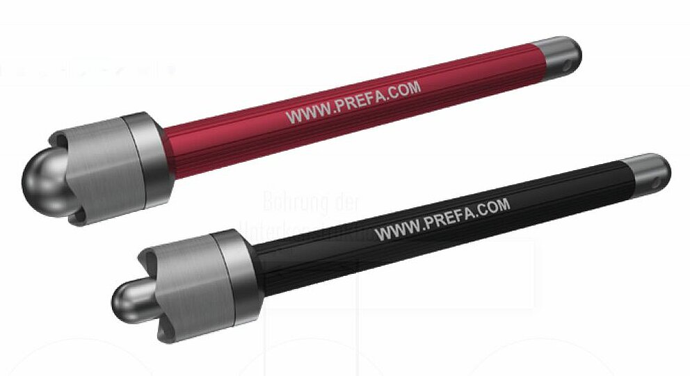
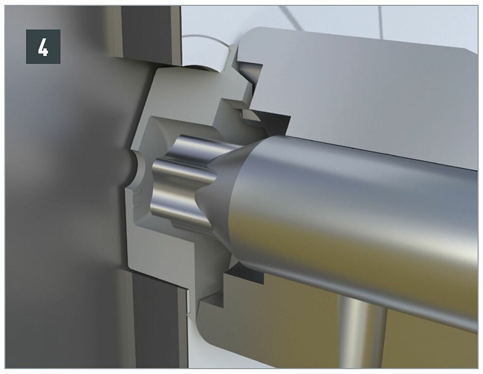
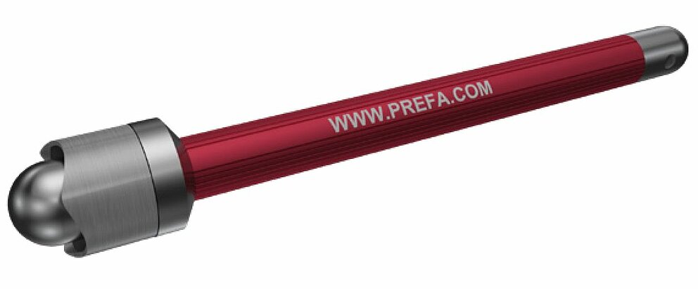
When riveting, regardless of whether it is a fixed or sliding point, always use the appropriate rivet nosepiece to prevent surface deformation and to ensure the panel can move (material expansion).
The rivet nosepiece is screwed onto a standard rivet gun (or riveting device) with threaded connection M10×1 mm.
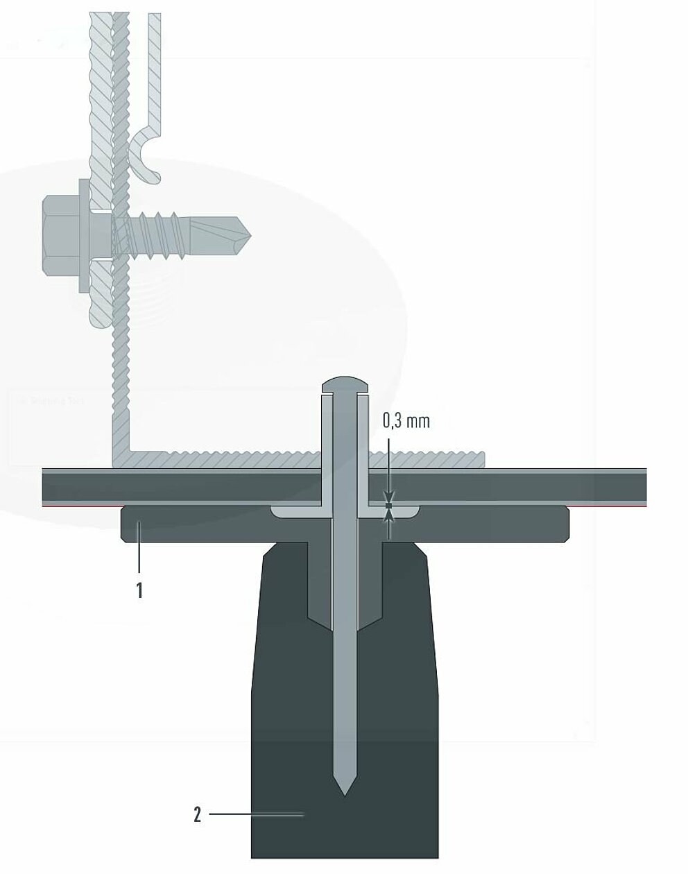
1 Rivet nosepiece |
2 Rivet fastener |
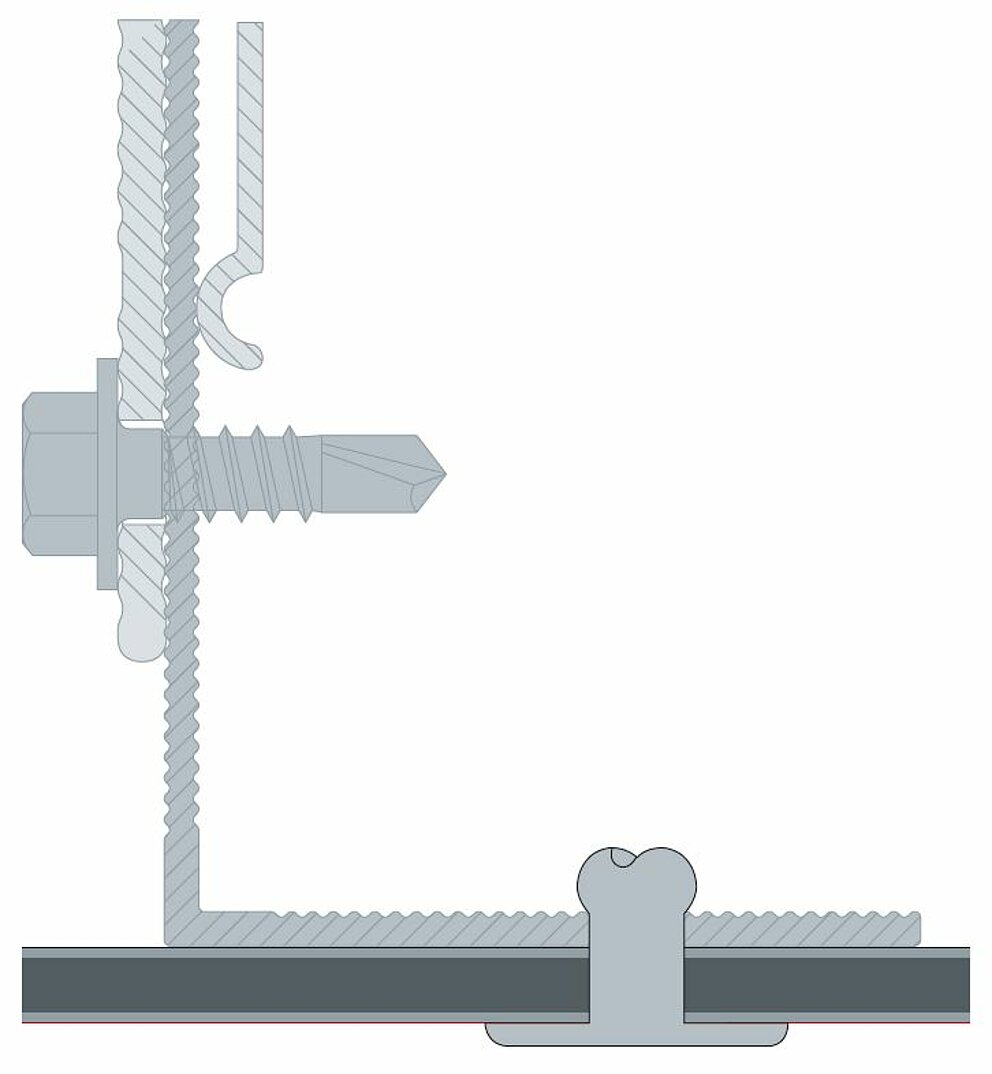
Fixed point
In this case, the panel cannot expand because the PREFABOND aluminum composite panel is firmly connected to the rails at this point.
To do this, the panels are pre-drilled using a ⌀ 5.1 mm or ⌀ 9.5 mm drill bit.
The metal rail is always pre-drilled with a hole size of ⌀ 5.1 mm.
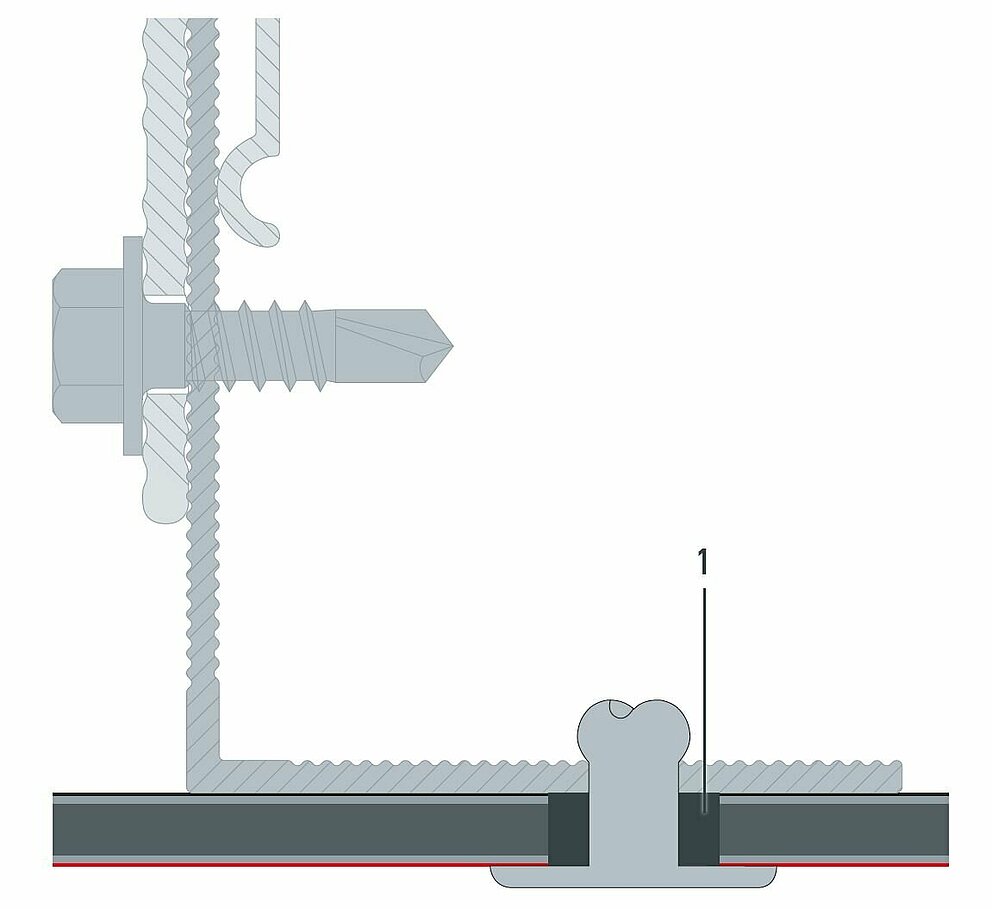
1 fixed point bushing |
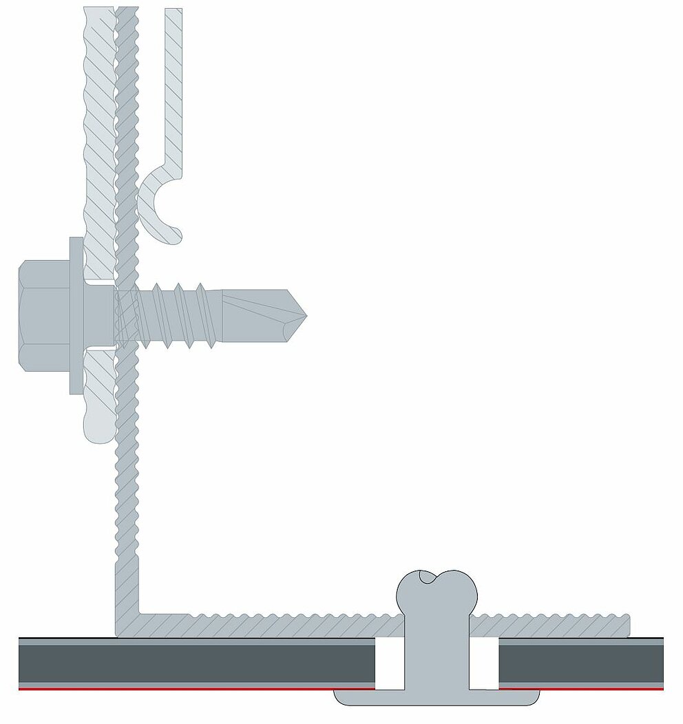
Sliding point
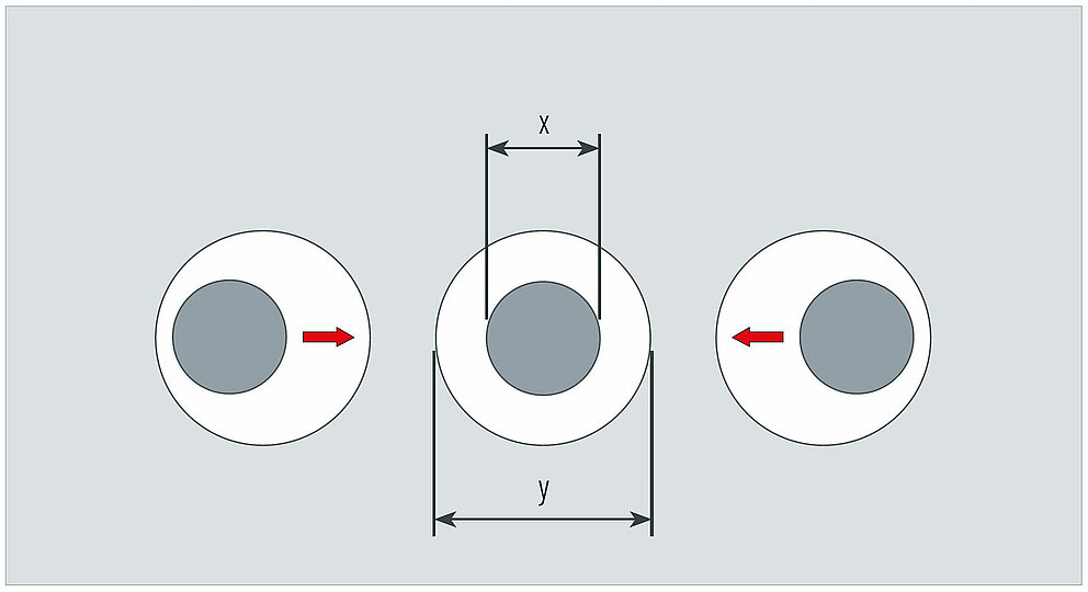
The bore hole is larger than the diameter of the fastener. All fastening holes of the panel are pre-drilled using a ⌀ 9.5 mm drill bit. The metal rail is always pre-drilled with a hole size of ⌀ 5.1 mm. This is the only way for a sliding point to be able to absorb the thermal material expansion of the panel.
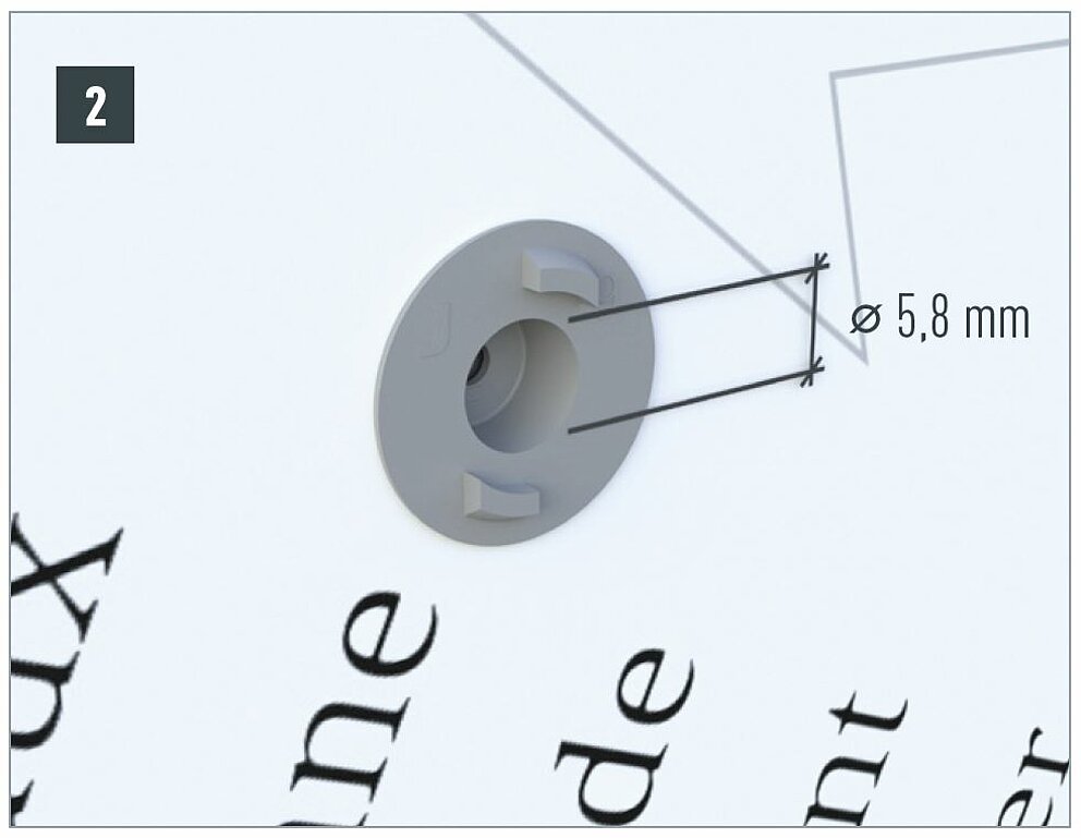
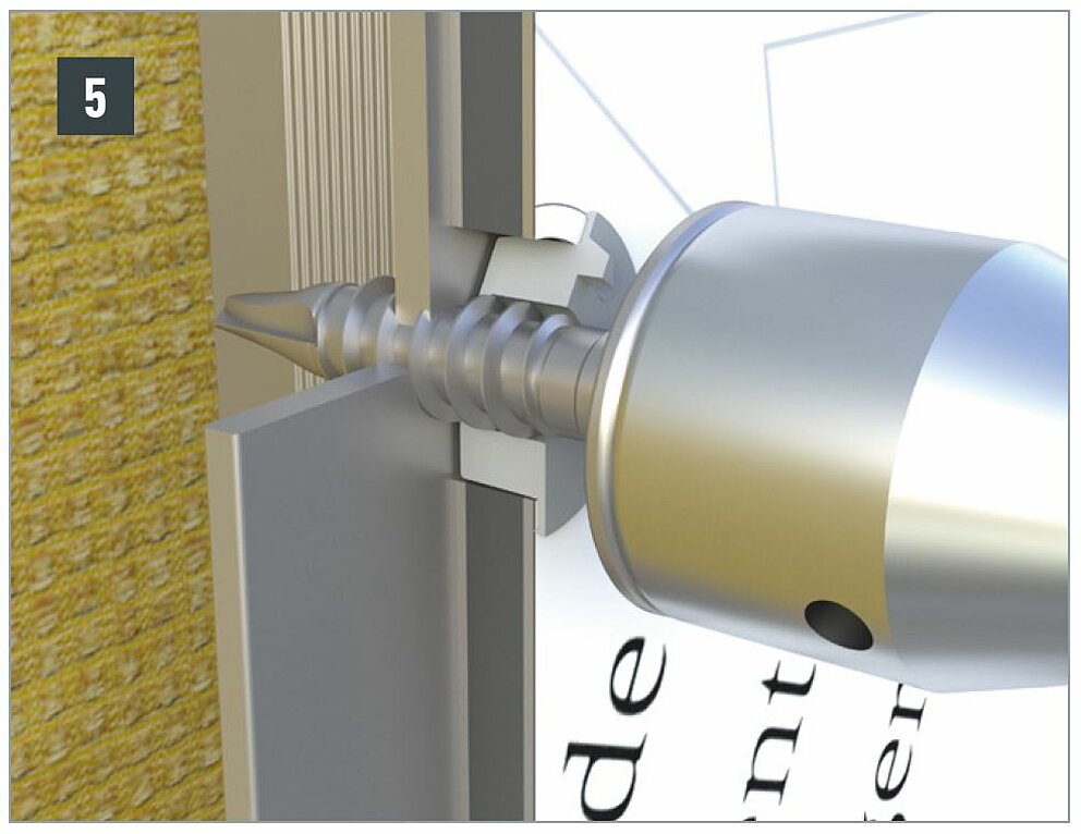
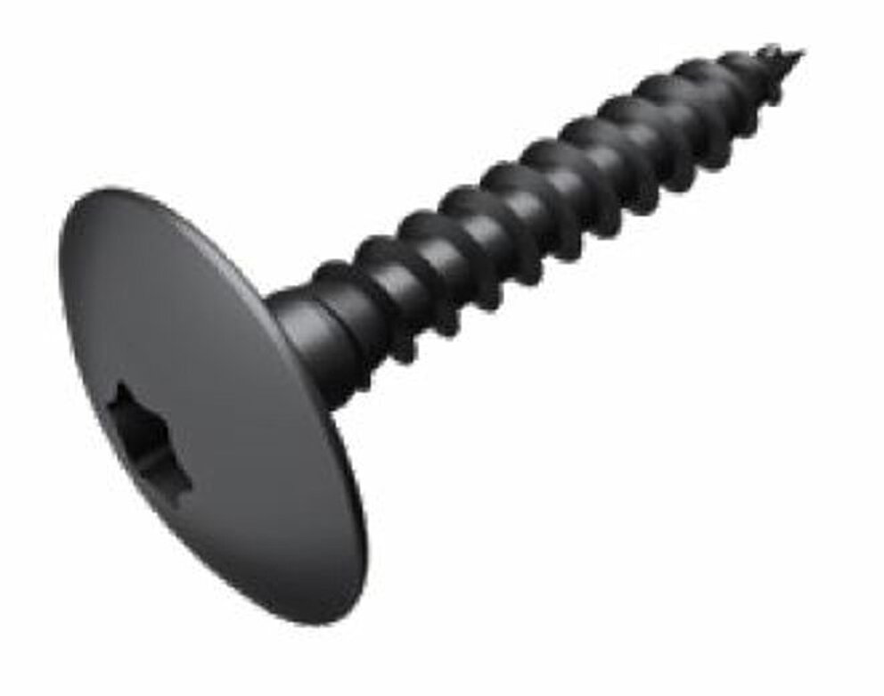
The screwed mechanical fastening system consists of a facade screw, a special LT-XT TOOL TX 25 bit and matching fixed and sliding point bushings.
In order to achieve centric drilling of the substructure, only use the centring bushing for fixed and sliding points that is matched to the fastening system.
Fixed point
Sliding point
In order to achieve centric drilling of the substructure, only use the appropriate bracket boring fixture which transfers the centre of the bore hole of a composite panel to the wooden substructure.
Use the PREFA ⌀ 9.5 mm film cutter to slightly score the protective film around the bore hole so that the protective film can be easily removed after the installation is complete. Otherwise, the film may become clamped between the panel and the bottom of the screw head, making it difficult to remove.
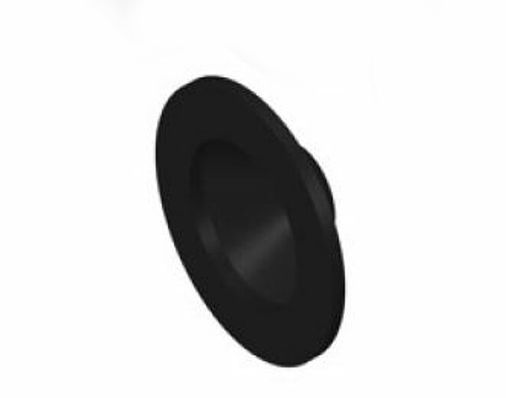
The hole size of the fastening points is always ⌀ 9.5 mm, regardless of whether it is a fixed or sliding point. The timber sub-structure framework is pre-drilled ⌀ 9.5 mm to ⌀ 3.3 mm using the bracket boring fixture for timber sub-structure frameworks in order to enable the screw to enter at right angles and centrically and to prevent the square timber from breaking out. Then press the façade-centring joint into each bore hole, regardless of whether it is a fixed or sliding point.
Note
In order to protect the wooden substructure from water penetrating it, it is important to apply a EPDM sealing tape to all vertical support profiles. This must protrude over the square timber by at least 5 to 10 mm on each side.
Fixed point
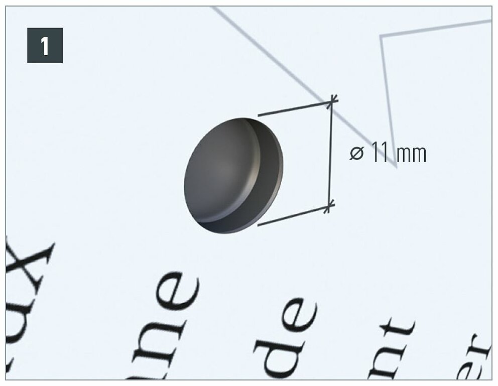
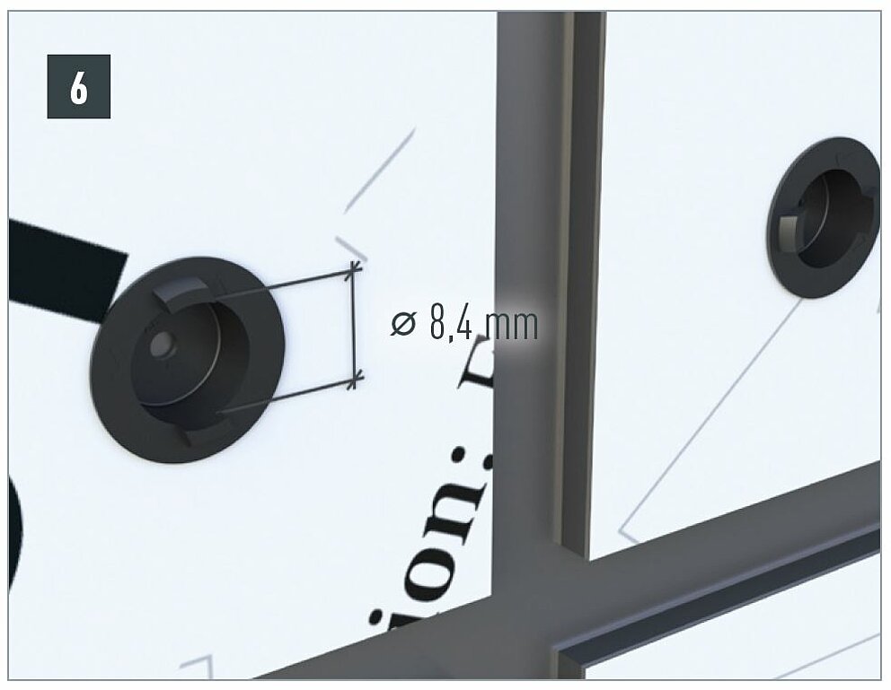
Since the PREFABOND aluminum composite panel is firmly connected to the wooden substructure at this point, a fixed point prevents the panel from moving. To obtain a fixed point, press the fixed point bushing ⌀ 8.5 mm to ⌀ 5.1 mm into the bore hole. In the next step, the screw can be screwed in.
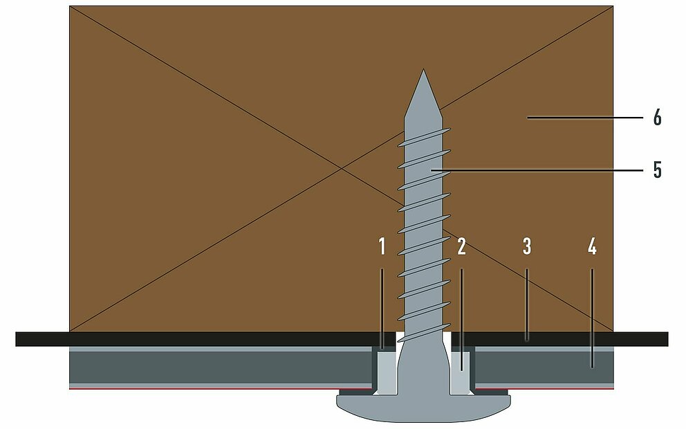
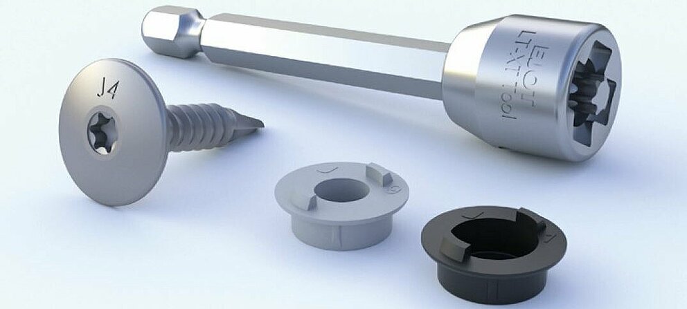
1 Façade-centring joint |
4 PREFABOND |
Note
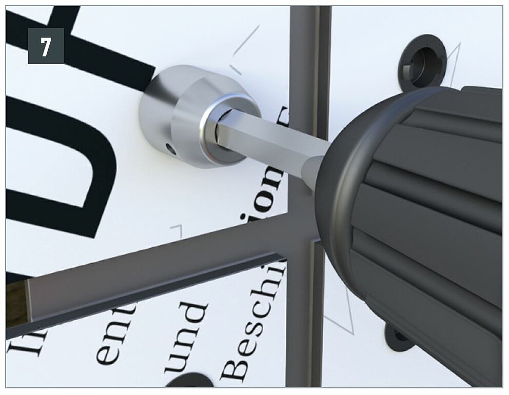
Tighten the screw with a moderate torque so that the screw holds the panel sufficiently in its position, but without pushing out the façade-centring joint from under the screw head.
Sliding point
For mechanical fastening to a wooden substructure, the sliding point is designed in the same way as the fixed point. The only difference is that no bushing is inserted into the façade-centring joint.
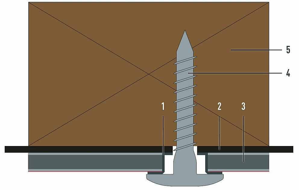
1 Façade-centring joint |
4 Façade screw |
1 Adhesive (beading) |
3 PREFABOND |
The following points must be taken into account for the supporting substrate:
The following points must be taken into account for the adhesive system:
The following points must be taken into account for the PREFABOND aluminium composite panel:
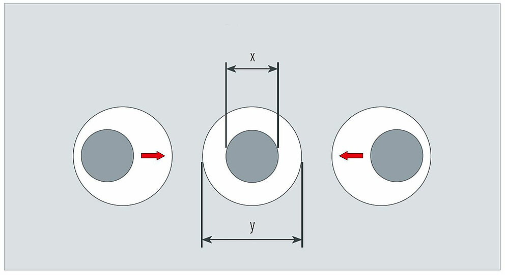
The horizontal spacing [X] between the vertical support profiles depends on the static requirements. Individual, building-related planning is essential.
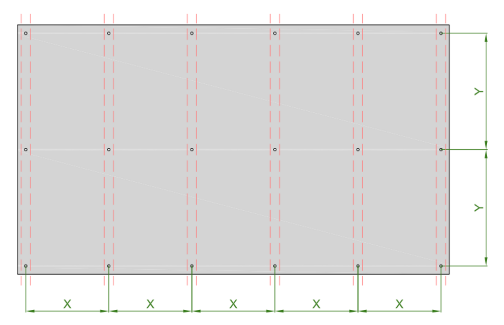
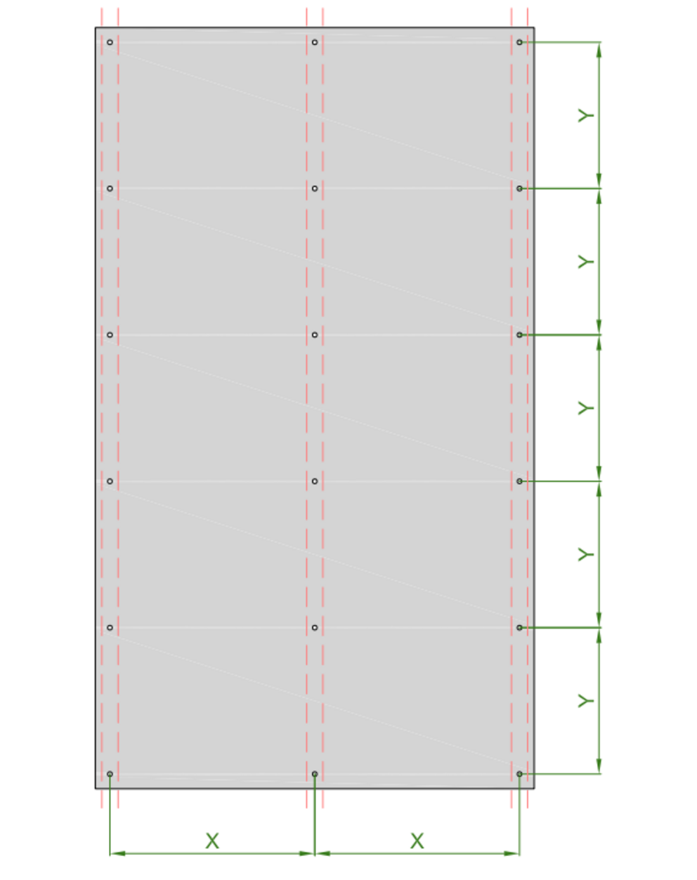
Y … (along the support profile) = max. 500 mm
X … center-to-center spacing of support profiles (mechanical fastening) = max. 800 mm
X … center-to-center spacing of support profiles (bonded fastening) = according to the adhesive manufacturer’s specifications
PREFA recommends that the sub-structure framework distances should not exceed 800 mm for mechanical fastenings. For bonded fastening, the sub-structure framework distances must be observed according to the adhesive manufacturer’s specifications. Otherwise, depending on the colour, gloss level and how the light falls, the surface may take on a wave-like appearance.
PREFABOND aluminium composite panels can be fastened either mechanically or abonded to soffits. Spacing of rails in a grid of 500 × 500 mm should not be exceeded.
Note
If the selected distance is too large, a crowning of the panel may become apparent, depending on the colour, gloss level and how the light falls.
You can only download content from one product category. If you require content from multiple categories, please create a separate download for each product area.